

ATtiny85 push-button power switching: software-only solution
- Emmanuel Odunlade
- https://twitter.com/emmaodunlade
- emmaodunlade@gmail.com
- 6.496 Views
- moderate
- Tested
In recent tutorials, we have highlighted how useful the ATtiny series of microcontrollers are, thanks to their tiny form factor and a decent amount of processing power, which makes them good choice for projects. where keeping a small device form factor is desired. One other feature that we probably have not highlighted enough, is their low power consumption which combined with their tiny form factor, would make perfect IoT devices. The prospects of their use in low power applications like IoT becomes even more clear when you consider the little amount of power they consume in different low-power modes. The Attiny85, for instance, consumes only 2uA in sleep mode.
Being able to switch between these modes will help you build more robust solutions with longer-lasting batteries using the Attiny series of Microcontrollers. Thus, to ensure you have all you need for this, today’s tutorial will focus on how to wakeup or turnoff the ATtiny85 microcontroller to save power or for any other reason you desire.
Taking the ATtiny85 in and out of sleep modes can be done in several ways including a fully automated software process involving a triggering element like an RTC, or the use of hardware components like a switch. Adopting any of these approaches depends on the requirements for your project but for today’s tutorial we will focus on triggering the sleep mode using a switch.
The tutorial will chronicle the example built by the good folks at bitbanging which implements two kinds of behaviors:
- Immediate push on/off: for this, the microcontroller will immediately go into sleep mode when the button is pressed, with all peripherals going off, and it will come back “on” when next the button is pressed
- Push and Hold for on/off: This will require the button to be pressed down for a particular timeframe before sleep mode is activated/deactivated.
Ready? let’s go
Required Components
The following components are required to recreate this project;
- ATtiny85
- SMD to DIP Socket
- Pushbutton
- LED
- 220 ohms Resistor
- battery/power supply (3.7V – 5V)
- Jumper wire
- Breadboard
All of these components can be purchased from your favorite online electronics component shops.
Schematics
The schematics for the project is quite straight forward. Connect the components as shown in the schematics below;
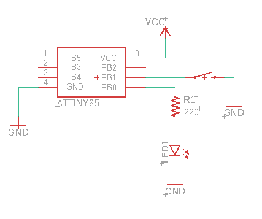
The LED, which is being used to indicate the state of the ATtiny (on/off), is connected to pin PB0 of the microcontroller via a resistor (current limiting), while the pushbutton is connected to pin PB1 which is an interrupt enabled pin. You will notice the Pushbutton connection does not have a pull-up (or pull-down) resistor. We will be using the microcontroller’s internal pull-up resistor to prevent the pin from floating.
With the connections complete, your setup should look like the image below.
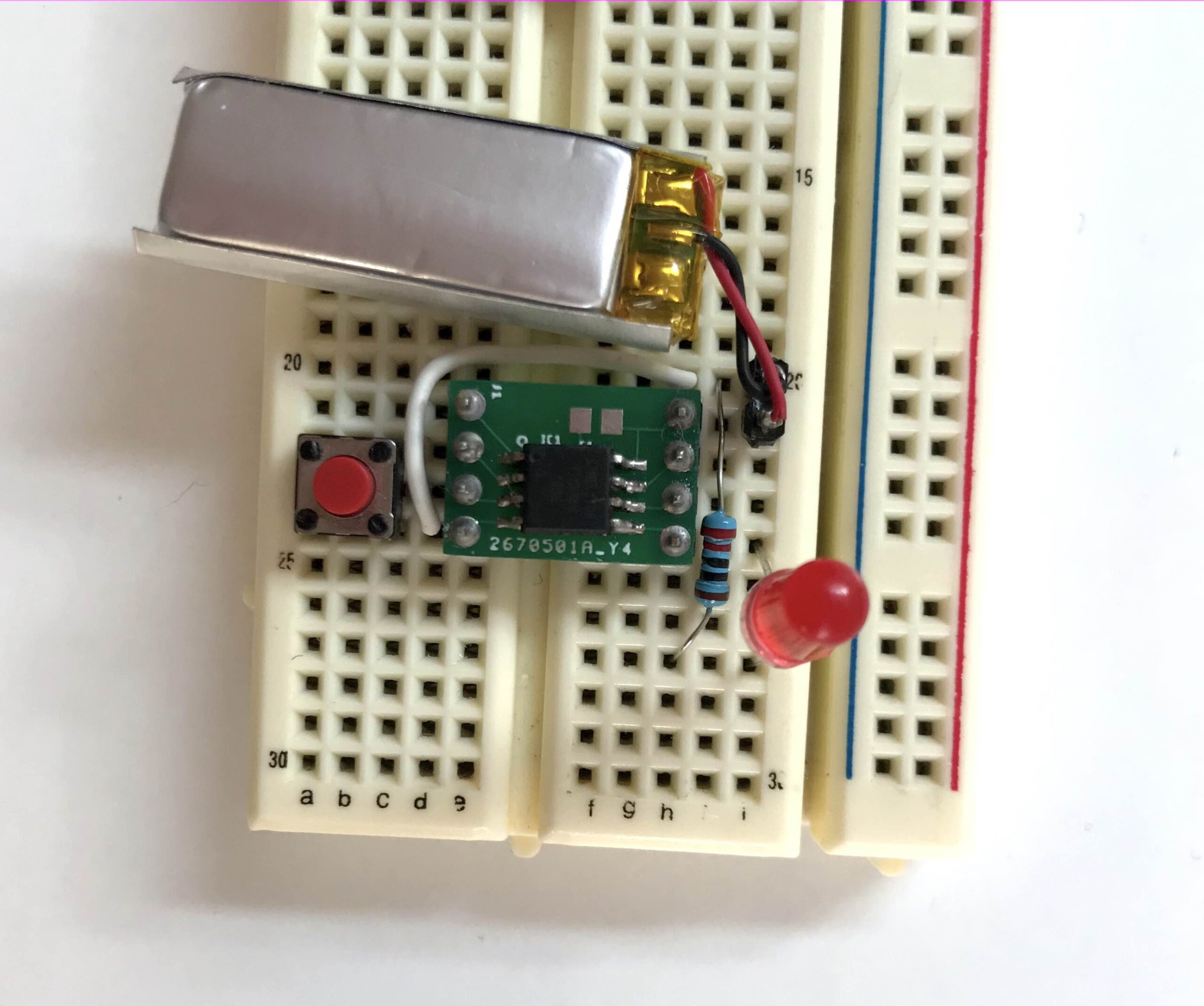
Go over it one more time to ensure there are no errors.
Code
While the schematic for both implementations is the same, and they both leverage interrupts, there are some differences in the code, so we will go over their codes separately. The firmware may be developed using AVR studio but if you are familiar with Arduino C, you can easily port it. We have covered several tutorials on programming ATtiny microcontrollers using the Arduino IDE.
1. Immediate Push ON / OFF
As mentioned earlier, for this implementation, we want the microcontroller to shutdown all peripherals and go to sleep when the button is pressed, and come back up the next time the button is pressed. The logic is simple; the current state of the device either on or off is stored in a variable, such that when a pin change interrupts is triggered by the push button, the device is driven from whatever state it is to the other state. So if the device was on (Running), the triggering of a pin change interrupt will take it to the off (POWER_OFF) state and vice versa.
As usual, I will do a brief run-through and explain some parts of it which I feel may be hard to follow.
We start, as usual, by including all the libraries that are required. I believe their names should easily give them away.
#include <avr/io.h>
#include <util/delay.h>
#include <avr/interrupt.h>
#include <avr/sleep.h>
#include <avr/wdt.h>
Next, we declare the I/O pin to which the pushbutton is connected and declare the integral constants for the “Status” variable.
#define BTN 1
#define BTN_STATUS !((PINB >> BTN) & 0x01)

enum Status
{
    RUNNING,
    POWER_OFF,
};
Next, we write the void power_off() function which dictates what happens when the microcontroller is to be switched off. The function includes commands to disable watchdog timer (WDT) and the Brown-out detector while putting the microcontroller in the PWR_DOWN sleep mode.
void power_off()
{
    cli();                               // Disable Interrupts before next commands
    wdt_disable();                       // Disable watch dog timer to save power
    set_sleep_mode(SLEEP_MODE_PWR_DOWN); // Set sleep mode power down
    sleep_enable();
    sleep_bod_disable(); // Disable Brown out detector
    sei();               // Enable interrupts
    sleep_cpu();
    sleep_disable();
}
Next, is the main function. The function starts with the interrupt setup, enabling the pull-up resistor on the pin and setting it as an interrupt pin. The default status of the device when powered is also set to running so that the first time the pin is pressed, it switches to the power-off mode.
int main()
{
    PORTB |= (1 << BTN);  // Enable PULL_UP resistor
    GIMSK |= (1 << PCIE); // Enable Pin Change Interrupts
    PCMSK |= (1 << BTN);  // Use PCINTn as interrupt pin
    sei();                // Enable interrupts

    status = RUNNING; // Start ON/OFF when power is connected

    DDRB |= (1 << DDB0); //Set pin 0 to output for the LE
Next, the main function listens for the interrupt trigger. If it is triggered and the state is set to running, the LED pin is turned “ON” and if it is triggered and status is set to power_off, the LED is turned off.
    for (;;)
    {
        if (status == RUNNING)
        {
            /* main code here */

            PORTB |= (1 << PB0); // LED Pin 0 ON

            /* -------------- */
        }
        else
        {
            PORTB &= ~(1 << PB0); // LED Pin 0 OFF

            power_off();
        }
    }
}
The last part of the code is the interrupt handling routine. The routine checks if the button has been pressed and changes the status based on the previous status.
ISR(PCINT0_vect)
{
    if (BTN_STATUS) //If button is down change status
    {
        if (status == RUNNING)
            status = POWER_OFF;
        else
        {
            status = RUNNING;
            /* initialize the device here (timers etc..)*/
        }
    }
}
The complete code for this implementation is provided below:
#include <avr/io.h>
#include <util/delay.h>
#include <avr/interrupt.h>
#include <avr/sleep.h>
#include <avr/wdt.h>

#define BTN 1
#define BTN_STATUS !((PINB >> BTN) & 0x01)

enum Status
{
    RUNNING,
    POWER_OFF,
};

void power_off()
{
    cli();                               // Disable Interrupts before next commands
    wdt_disable();                       // Disable watch dog timer to save power
    set_sleep_mode(SLEEP_MODE_PWR_DOWN); // Set sleep mode power down
    sleep_enable();
    sleep_bod_disable(); // Disable Brown out detector
    sei();               // Enable interrupts
    sleep_cpu();
    sleep_disable();
}

Status status;  // Device status

int main()
{
    PORTB |= (1 << BTN);  // Enable PULL_UP resistor
    GIMSK |= (1 << PCIE); // Enable Pin Change Interrupts
    PCMSK |= (1 << BTN);  // Use PCINTn as interrupt pin
    sei();                // Enable interrupts

    status = RUNNING; // Start ON/OFF when power is connected

    DDRB |= (1 << DDB0); //Set pin 0 to output for the LED

    for (;;)
    {
        if (status == RUNNING)
        {
            /* main code here */

            PORTB |= (1 << PB0); // LED Pin 0 ON

            /* -------------- */
        }
        else
        {
            PORTB &= ~(1 << PB0); // LED Pin 0 OFF

            power_off();
        }
    }
}

ISR(PCINT0_vect)
{
    if (BTN_STATUS) //If button is down change status
    {
        if (status == RUNNING)
            status = POWER_OFF;
        else
        {
            status = RUNNING;
            /* initialize the device here (timers etc..)*/
        }
    }
}
2. Push and Hold for on/off
The major difference between this and the first implementation is the desire to introduce a delay. The user has to hold the pushbutton down for a particular period of time before we register it as ON, and the same thing needs to happen to switch the device OFF.
To record how long the button has been pressed, we will be using a timer which will generate an interrupt approximately every millisecond and the interrupt service routine will increment a timer variable until the set time is reached.
Like the first implementation, I will do a brief run through and explain parts of the code which I feel may be hard to follow.
As usual, we start the code by including the libraries to be used.
#include <avr/io.h>
#include <util/delay.h>
#include <avr/interrupt.h>
#include <avr/sleep.h>
#include <avr/wdt.h>
Next, we define the pin to which the button is connected, initialize the time and set the period of time for which the button must be pressed for it to register to 1000ms.
#define BTN 3
#define timer_init() (TIMSK |= (1 << OCIE0A))
#define BTN_HOLD_MS 1000    // Press button for 1 second
Next, we declare the integral constants for the “Status” variable and also create variables to hold the status of the button (Notice this was not done in the previous implementation?).
enum Device_Status
{
    POWER_OFF,
    RUNNING
};
enum Btn_Status
{
    BTN_UP,
    BTN_DOWN,
    BTN_IGNORE
};
Next, we write the setup() function. Here we simply did things that are similar to what you would have done in the setup function of an Arduino sketch. We enabled pull-up resistors, and interrupts on pins etc. each line is commented so it should be easy to follow.
void setup()
{
    sei();                  // Enable interrupts
    PORTB |= (1 << BTN);    // Enable PULL_UP resistor
    GIMSK |= (1 << PCIE);   // Enable Pin Change Interrupts
    PCMSK |= (1 << BTN);    // Use PCINTn as interrupt pin (Button I/O pin)
    TCCR0A |= (1 << WGM01); // Set CTC mode on Timer 1
    TIMSK |= (1 << OCIE0A); // Enable the Timer/Counter0 Compare Match A interrupt
    TCCR0B |= (1 << CS01);  // Set prescaler to 8
    OCR0A = 125;            // Set the output compare reg so tops at 1 ms
}
Next, we write the power_off() function. This is similar to the one used for the first implementation.
void power_off()
{
    cli();                               // Disable interrupts before next commands
    wdt_disable();                       // Disable watch dog timer to save power
    set_sleep_mode(SLEEP_MODE_PWR_DOWN); // Set sleep mode power down
    sleep_enable();
    sleep_bod_disable(); // Disable brown-out detector
    sei();               // Enable interrupts
    sleep_cpu();
    sleep_disable();
}
Next, we write the main function.
The function starts by calling the setup function to implement everything grouped under it. Next, we initialize the device status to running, pushbutton status to “btn_up” and set the pin to which the LED is connected as an output pin.
int main()
{
    setup();
    Device_Status status = RUNNING; // Set start ON or OFF when power is connected
    btn_status = BTN_UP;
    DDRB |= (1 << DDB0); // Set pin 0 as output
Next, we write if…else statements to trigger the LED, based on the Device_Status as determined by the status of the push button.
  for (;;)
    {

        if (btn_status == BTN_DOWN)
        {
            if (timer > BTN_HOLD_MS) // Check if button has been pressed enough
            {
                if (status == RUNNING)
                    status = POWER_OFF;
                else
                {
                    status = RUNNING;
                    // setup of the device here if needed;
                }
                btn_status = BTN_IGNORE; // If status already changed don't swap it again
            }
        }
        else
        {
            if (status) // Is status RUNNING?
            {
                /* main code here */

                PORTB |= (1 << PB0); // Pin 0 ON

                /* -------------- */
            }
            else
            {
                PORTB &= ~(1 << PB0); // Pin 0 OFF
                power_off();
            }
        }
    }
}
Next, we write the interrupt service routine that checks if the button has been pressed or not to kickstart timer, and the routine that increments the timer.
ISR(PCINT0_vect)
{
    if (!((PINB >> BTN) & 0x01)) // Check if button is down
    {
        btn_status = BTN_DOWN;
        timer_init();
        timer = 0;
    }
    else
        btn_status = BTN_UP;
}

ISR(TIM0_COMPA_vect)
{
    timer++;
The complete code for this implementation is provided below;
#include <avr/io.h>
#include <util/delay.h>
#include <avr/interrupt.h>
#include <avr/sleep.h>
#include <avr/wdt.h>

#define BTN 3
#define timer_init() (TIMSK |= (1 << OCIE0A))
#define BTN_HOLD_MS 1000    // Press button for 1 second

enum Device_Status
{
    POWER_OFF,
    RUNNING
};
enum Btn_Status
{
    BTN_UP,
    BTN_DOWN,
    BTN_IGNORE
};

void setup()
{
    sei();                  // Enable interrupts
    PORTB |= (1 << BTN);    // Enable PULL_UP resistor
    GIMSK |= (1 << PCIE);   // Enable Pin Change Interrupts
    PCMSK |= (1 << BTN);    // Use PCINTn as interrupt pin (Button I/O pin)
    TCCR0A |= (1 << WGM01); // Set CTC mode on Timer 1
    TIMSK |= (1 << OCIE0A); // Enable the Timer/Counter0 Compare Match A interrupt
    TCCR0B |= (1 << CS01);  // Set prescaler to 8
    OCR0A = 125;            // Set the output compare reg so tops at 1 ms
}

void power_off()
{
    cli();                               // Disable interrupts before next commands
    wdt_disable();                       // Disable watch dog timer to save power
    set_sleep_mode(SLEEP_MODE_PWR_DOWN); // Set sleep mode power down
    sleep_enable();
    sleep_bod_disable(); // Disable brown-out detector
    sei();               // Enable interrupts
    sleep_cpu();
    sleep_disable();
}

volatile unsigned int timer;  // milliseconds counter
Btn_Status btn_status;        // Status of the button

int main()
{
    setup();
    Device_Status status = RUNNING; // Set start ON or OFF when power is connected
    btn_status = BTN_UP;
    DDRB |= (1 << DDB0); // Set pin 0 as output

    for (;;)
    {

        if (btn_status == BTN_DOWN)
        {
            if (timer > BTN_HOLD_MS) // Check if button has been pressed enough
            {
                if (status == RUNNING)
                    status = POWER_OFF;
                else
                {
                    status = RUNNING;
                    // setup of the device here if needed;
                }
                btn_status = BTN_IGNORE; // If status already changed don't swap it again
            }
        }
        else
        {
            if (status) // Is status RUNNING?
            {
                /* main code here */

                PORTB |= (1 << PB0); // Pin 0 ON

                /* -------------- */
            }
            else
            {
                PORTB &= ~(1 << PB0); // Pin 0 OFF
                power_off();
            }
        }
    }
}

ISR(PCINT0_vect)
{
    if (!((PINB >> BTN) & 0x01)) // Check if button is down
    {
        btn_status = BTN_DOWN;
        timer_init();
        timer = 0;
    }
    else
        btn_status = BTN_UP;
}

ISR(TIM0_COMPA_vect)
{
    timer++;
}
That’s it!
IoT or not, there will always be a need to put any device (the entire device or some part of the device e.g display in mobile phones) running of battery in sleep mode. The approach to this will differ based on the core functions of the device but whichever way it is snippets from the code shared above can be leveraged to achieve this.
.png)


")

I really appreciate your work I’ve tried it and it’s working flawlessly, for anyone want to try this so you just don’t get confused push button is pin3 not pin1
Thank you for pointing this out. I was so confused why this wasn’t working.
Nice piece of coding.
I have been trying for 2 days now to get this to work with an IR receiver, replacing the button.
Looks like the IR receiver throws out a lot of ‘pulses’ resulting in LED ON.
To be able to distinguish between on/off I implemented #include <IRremote.hpp>
Before this change (your code) the power consumption is 0.33mA
After my change, the power consumption is 4.4 mA
Any idea how this could work with same low power consumption (AX-1838HS consumes 1.5 mA so my goal is 1.83mA).