Arduino Nokia 5110 Tutorial #2- Displaying Customized Graphics
- Nick Koumaris
- http://educ8s.tv/
- info@educ8s.tv
- 14.780 Views
- moderate
- Tested
Introduction
In one of our previous tutorials we did an introduction on how to use the Nokia 5110 LCD with the Arduino, the tutorial covered displaying texts with different fonts etc. For this tutorial, we are taking things a little bit further and will be working through the display of customized graphics on the Nokia 5110 LCD display. This tutorial will particularly be useful for those who want to display their brand logo or any other kind of image on the LCD asides ordinary texts.
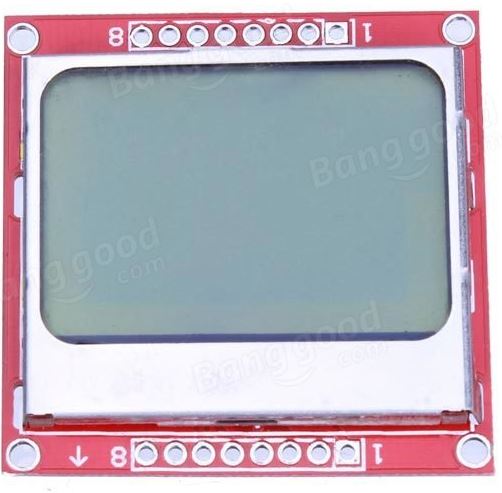
The Nokia 5110 display is basically a graphic LCD display useful for a lot of applications. It was intended originally to be used as a screen for cell phones and was used in lots of mobile phones during the 90’s. This display uses a low powered CMOS LCD controller/driver PCD8544, which drives the graphic display of size 84×48. In a normal state, the display consumes about 6 to 7mA which makes it quite ideal for low power usage.
A detailed explanation on the operational principle of the display is found here.
Requirements
Both software and hardware requirements exist for this tutorial. To start with the hardware;
Required Components
The following components will be needed for this tutorial;
Required Software
The following software tools will be used for this tutorial.
- Microsoft Paint/Corel draw/ Photoshop/paint.net
- LCD Assistant Software
Schematics
To interface with a micro controller and power itself, the display has two parallel 8-pin port to which headers pins can be connected. You can pick one of the sides and solder header pins to it for connection to the Arduino board.
There are two main power sources needed. The first one is the operational power supply which according to the data sheet should be between the range of 2.7V to 3.3V. The second power supply is required for the LCD back-light. The LCD circuit has no current limiting resistor inbuilt so its better to play safe and only power with 3.3V max.
The LCD is connected to the Arduino as shown in the Schematics below.
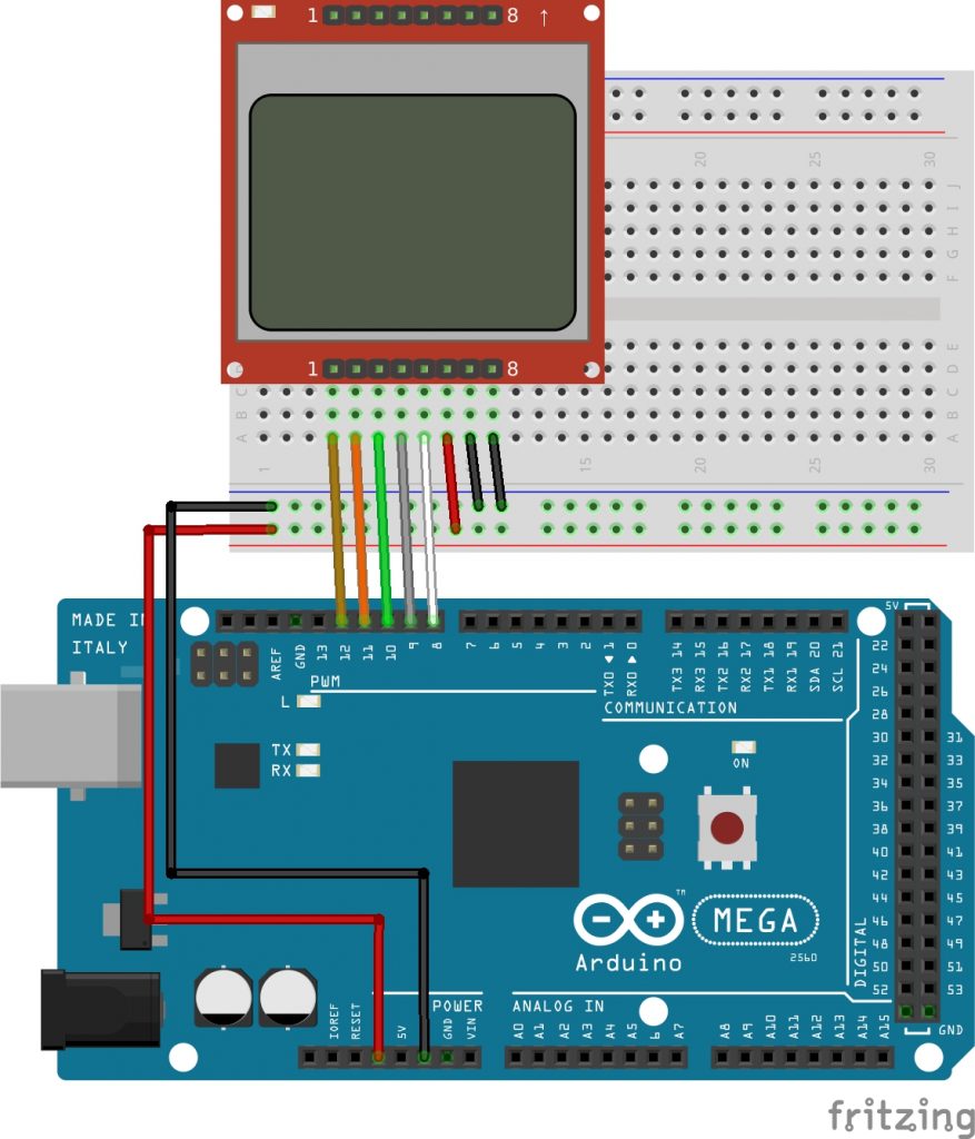
The connection is illustrated below.
Display - Arduino
Pin 1(RST) – D12
Pin 2(CE) – D11
Pin 3(DC) – D10
Pin 4(DIN) – D9
Pin 5(CLK) – D8
Pin 6(VCC) - VCC
Pin 7(LIGHT) - GND
Pin 8(GND) - GND
Preparing the Graphics
After connecting the LCD to our Arduino, the next line of action is to prepare the graphics to be displayed.
The graphics can be created using tools like, Microsoft paint, Corel draw, Paint.net or Adobe Photoshop. The important thing is to ensure the image is saved as a bitmap.
For the purpose of this tutorial, we will be using the paint.net tool to create the graphics. It is easy to use and can be downloaded from here. One thing that should be kept in mind while creating the graphics or logo is the canvass size. Since the LCD is 84×48, its important the canvass size is same as the screen, to ensure the designed graphics shows perfectly on the display.
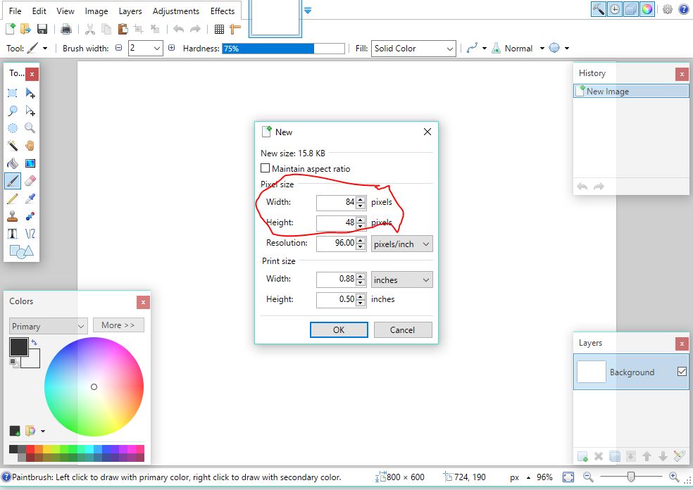
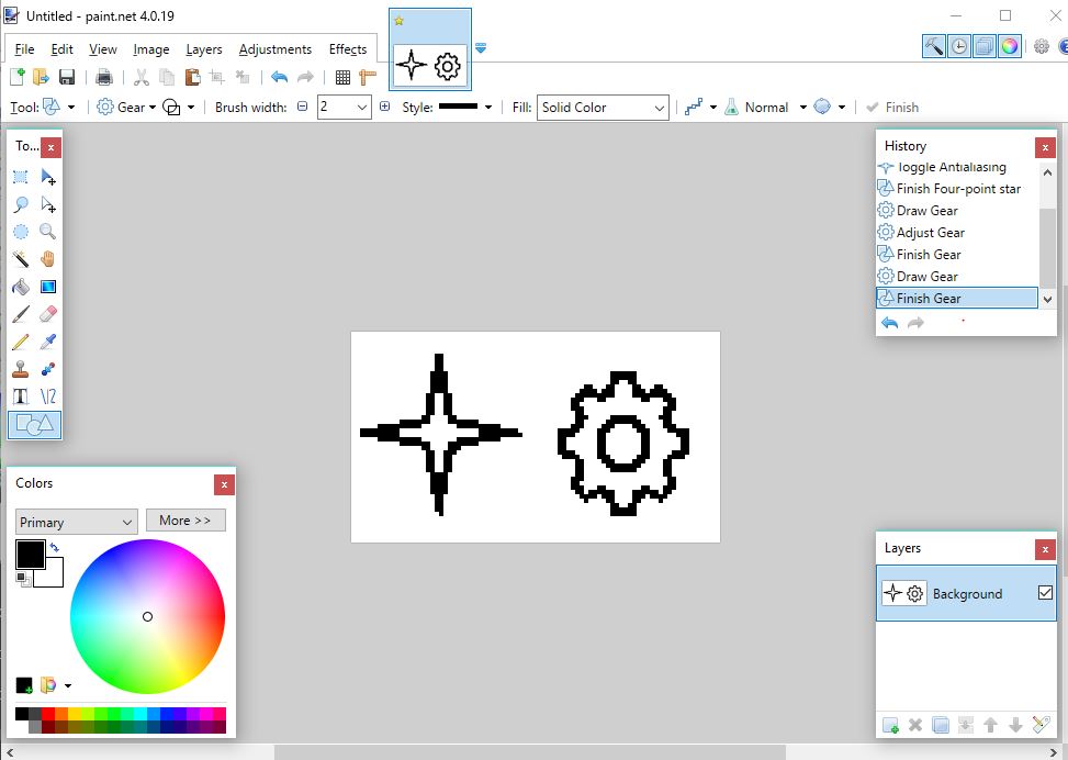
In order to load our own graphics into the Arduino to be displayed by the Nokia 5110 display, we will need to use the LCD assistant software. It is a free and easy to use software that converts bitmap images into a data array which can then be used in C programming language based firmware for any micro-controller. The software is available for download here.
To convert the Bitmap Image into a data array, the bitmap image is loaded into the LCD Assistant software.
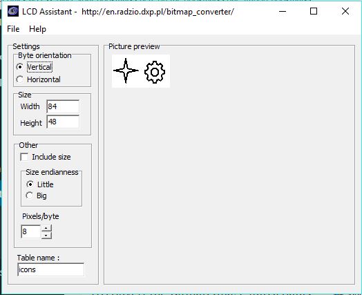
Then save output (Also found under file) as Graphics.c. The file can be previewed using a tool like notepad++ and your output should look something like the image below.
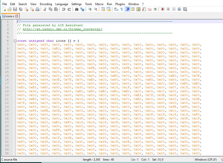
With this done, we are then ready to import the C file into our Arduino code.
For better performance, we can save the data array in the program memory of the arduino instead of the sram, to save as much space as possible. To do this we will need to include some line of code to the data array file as shown in the image below.

The data array generated is attached in the zip file at the end of this tutorial.
Code
The Arduino code for this project is a fairly simple one, especially if you have checked out the previous tutorial on Nokia 5110 LCD Display Module.
The first thing we do is include the LCD5110 graph library by Henning Karlsen which can be downloaded here.
//Written by Nick Koumaris
//info@educ8s.tv
//educ8s.tv
#include <LCD5110_Graph.h>
After including the library, we then declare the pins on the Arduino to which the LCD is connected.
LCD5110 lcd(8,9,10,12,11);
Moving on, we declare the various graphics that will be used. For this example, we will be using three different graphics ( Icons, pi, cube) all loaded in the same Graphics.c file. Check the attached Graphics.c file attached at the end of the tutorial to see how they were merged.
extern uint8_t icons[];
extern uint8_t pi[];
extern uint8_t cube[];
We then move into the setup function and initialize the LCD.
void setup()
{
  lcd.InitLCD();
}
With the LCD initialized, we then move to the loop proper. For each of the graphics to be displayed, we first clear the screen using lcd.clrscr() and then draw the graphics using lcd.drawbitmap() with the coordinates, name of the file, and the size as parameters. update the display with lcd.update() and set a delay to give the graphics enough time to display on the screen.
void loop()
{
  lcd.clrScr();
  lcd.drawBitmap(0,0,pi,84,48);
  lcd.update();
  delay(2000);

  lcd.clrScr();
  lcd.drawBitmap(0,0,icons,84,48);
  lcd.update();
  delay(2000);

  lcd.clrScr();
  lcd.drawBitmap(0,0,cube,84,48);
  lcd.update();
  delay(2000);

}
The full code for the project:
//Written by Nick Koumaris
//info@educ8s.tv
//educ8s.tv
#include <LCD5110_Graph.h>

LCD5110 lcd(8,9,10,12,11);

extern uint8_t icons[];
extern uint8_t pi[];
extern uint8_t cube[];

void setup()
{
  lcd.InitLCD();
}

void loop()
{
  lcd.clrScr();
  lcd.drawBitmap(0,0,pi,84,48);
  lcd.update();
  delay(2000);

  lcd.clrScr();
  lcd.drawBitmap(0,0,icons,84,48);
  lcd.update();
  delay(2000);

  lcd.clrScr();
  lcd.drawBitmap(0,0,cube,84,48);
  lcd.update();
  delay(2000);

}
Demo
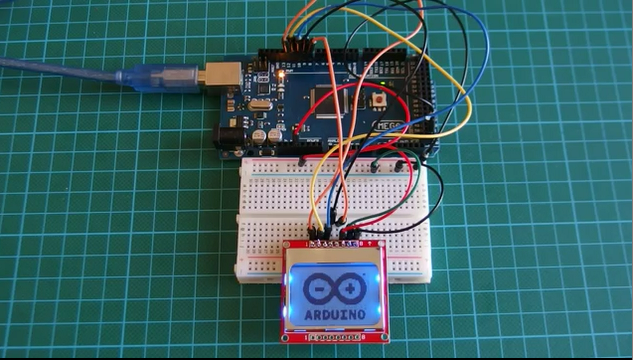
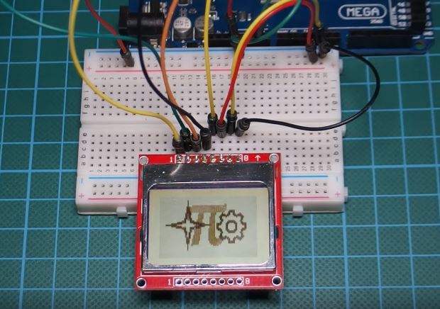
Copy the code, paste in the Arduino IDE, and upload to your Arduino board, you should get an output like the image below on your screen. Don’t forget to include the Graphics.c file in the Arduino sketch folder.
That’s it for this tutorial guys. As usual, let me know via the comment section, if you have any questions.
Happy holidays!
The youtube video of this tutorial is available here.


.png)



Hi. In your previous and interesting article about Nokia 5110, you have shown a Fritzing picture of the wiring. These wires are connected into a different way respect the sketch and also respect the Fritzing picture used in this article. Could you tell me how much freedom permit the library, choosing the pins of Arduino?
Thank you.
Hi, Thanks for your comment. in most siltuations, fritzing schematics are just representatives as the exact replica of that particular component may not be available on fritzing. This is the reason why i add the pin maps. To really know how the components should be connected, you can use the pin maps.
regards.
I’m not sure what I’m doing wrong here. I’m just trying to use the file as is and I keep getting errors for each graphic in the file. Example: lcd.ino:21: undefined reference to `pi’
I found the problem. It’s because the Graphics file was using a “.C” for the file exertion when it should be a “.c”