Chirp for Arduino – Send Data Over the Air with Sound
- Emmanuel Odunlade
- https://twitter.com/emmaodunlade
- emmaodunlade@gmail.com
- 5.160 Views
- medium
- Tested
With IoT expanding, developers are begining to desire more communication options to facilitate the exploration of diverse IoT possibilities. This was one of the reasons why the announcement of partnership between Chirp and Arduino was received with so much enthusiasm by the makers. Arduino has established itself as one of the biggest names in the ecosystem attached with its easy/ready to use hardware, while Chirp is arguably the most robust Data over Sound communication platform, as such, a lot of people believe the collaboration will not only bring Chirp’s functionalities into Arduino but it will also make the corresponding functionalities easy to use. For today’s tutorial, we will look at how you can implement Chirp’s Data over Sound communication in your Arduino Project.
Data over sound is the process of converting information into audible or inaudible frequencies that get transmitted with a speaker and that can be received with the help of a microphone and Chirp is currently one of the best ways to do it. The Chirp SDK encodes the message you want to send into a series of sounds that form an audio barcode that can be played back with any device that has a loudspeaker. Devices that have a microphone can then listen for these codes and decode them to restore the original message.
Chirp adds a completely unique transport mechanism to Arduino boards. The added capabilities of data-over-sound means that makers have more connectivity options at their fingertips. Some of the advantages of data-over-sound include:
- Device agnostic: data can be sent from mobile apps, web pages, or even with just an audio file
- One to many: any device within hearing range is able to receive data in one simple transaction
- Frictionless: doesn’t need any pairing, passwords or initial setup
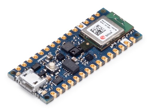
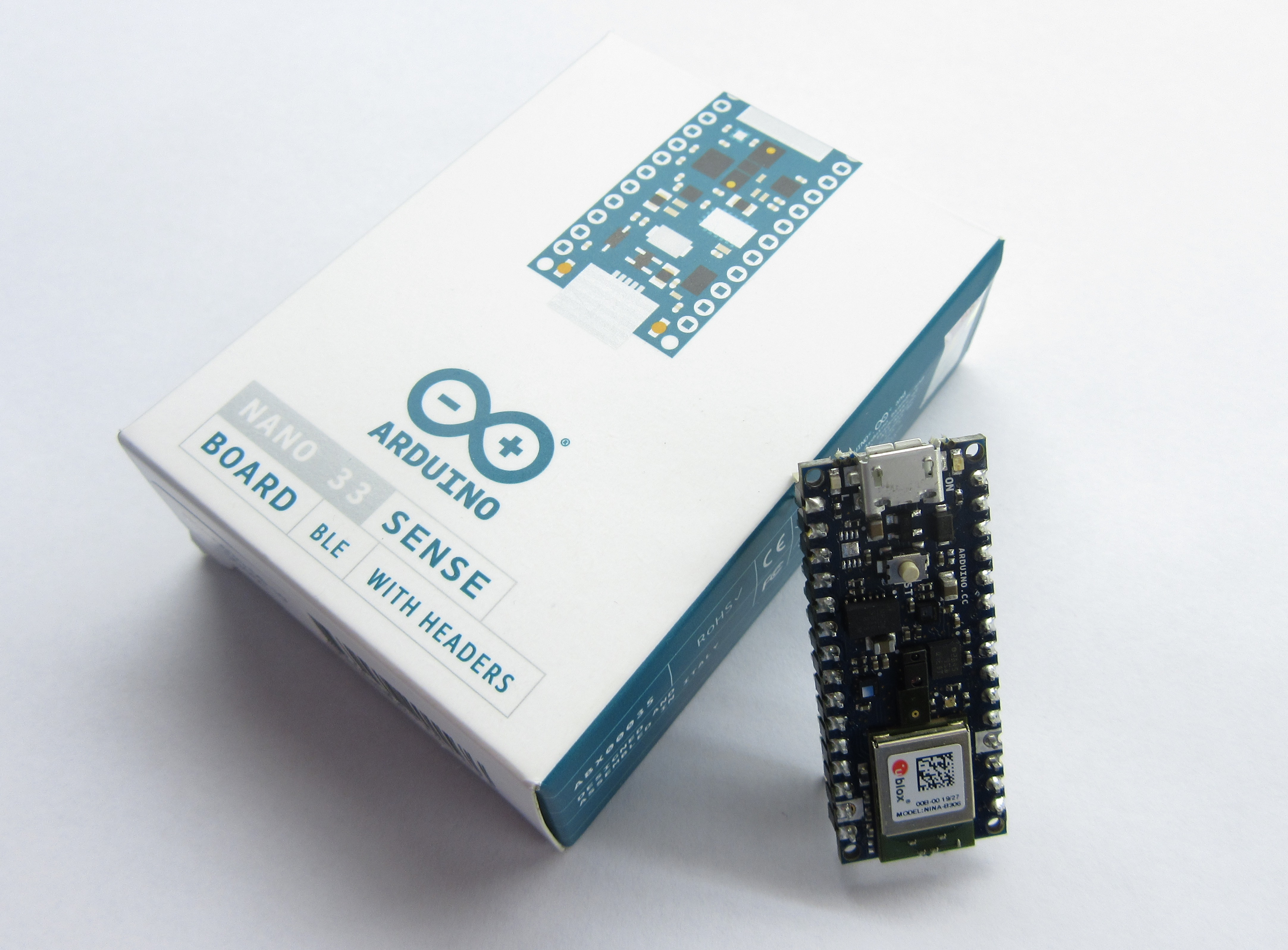
To demonstrate how to use Chirp features with the Arduino, we will build a simple project which changes the color of an attached LED in line with an RGB value received via audio signal. For this project, we will use the new Arduino “Nano 33 Sense” board which is one of the latest Arduino boards with a wide range of onboard sensors and features including an onboard microphone that is optimized for Chirp.
Required Components
Everything we need for this tutorial including the RGB LED, and Microphone, comes with the Nano 33 Sense board, making it the only thing needed for the tutorial. However, to be able to better observe the change in color, you may decide to use an external RGB LED asides the one onboard. To do that, you will need:
- The Nano 33 Sense Arduino Board
- 220 ohms Resistor
- RGB LED
- Breadboard
- Jumperwires
Schematics
Going with the onboard RGB LED means you do not need to worry about schematics or connections as everything you need including the mic and the LED already comes with the board.
Getting Ready
Before we write the code for the project, we need to sign-up to Chirp to obtain the necessary credentials like the app key, the app secret and audio configuration as they will be required for our code.
Follow the steps below to complete your chirp sign up and obtain necessary details. If you have a Chirp account already, you can jump to step 3.
- Visit the Developers section of the Chirp website and click on the sign up button.
- On the resulting page, Choose the sign in with Google option or just fill in the details and hit the sign up button at the end of the page.
- With sign up complete, you will be automatically directed to a “configure your application” page. This page is where you choose which of the Chirp protocol you will use for your project and the app key, secret and config will be automatically generated. Chirp currently supports 5 protocols with different audio transmission properties but for this tutorial, we will use the 16khz-mono-embedded protocol as it is the one currently supported for Arduino. Select it from the drop-down menu under the configuration section and click on the SAVE button.
- Your APP key, APP secret, and Configuration should now be generated. Copy them to a safe place as we will use them in the Arduino Sketch.
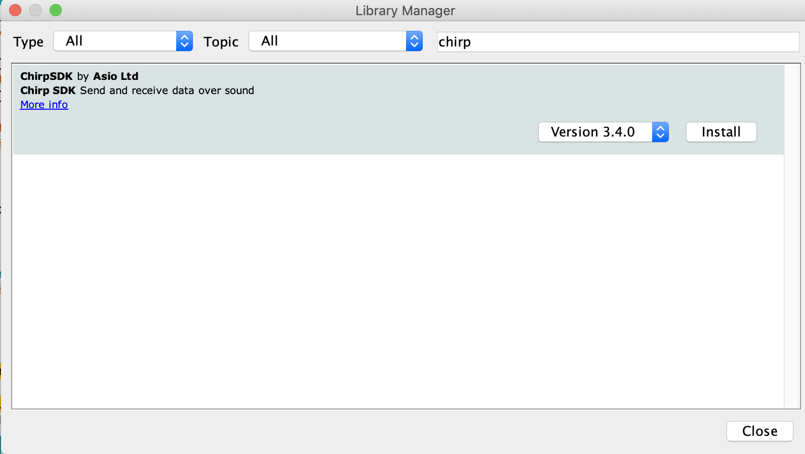
Another thing we need to do is to prepare the Arduino IDE by installing the Chirp SDK on it. Go to the Arduino Library manager (via Tools -> Manage Libraries) and enter “Chirp SDK” in the search bar. You will see the SDK listed as shown below.
Click the install button and close the manager when done.
We are now ready to write the code for the project. However, ensure you are using the latest version of the IDE as older versions may not come with the Nano 33 Sense board installed although it can be installed via the IDE board manager.
Code
The code for this project is a modification of the receiver example attached to the Chirp SDK we installed earlier.
The thought process behind the code is simple. The devices stay on the lookout for audios matching that of its protocol. When the matching sound is received, it evaluates it and extracts the message stored in it. The message, which in this case is an RGB value, is then used to set the color of the connected (onboard) RGB LED.
Asides the Chirp SDK which we mentioned earlier, we will also use the PDM (Pulse Density Modulation) library. The PDM library will be installed when adding the Nano 33 Sense board via Boards Manager and makes it easy to work with PDM microphones like the MP34DT05 onboard the Nano 33 Sense.
As usual, I will do a brief explanation of the sketch, explaining sections I feel might be difficult to understand. We start the sketch by including these libraries mentioned above along with the Credentials.h file. The credentials.h file should be located in the same folder as your code. Ensure the chirp credentials we obtained earlier are filled accurately in it.
#include <PDM.h>
#include "chirp_sdk.h"
#include "credentials.h"
Next, we create variables to indicate the audio sampling rate, buffer size and pointers to the pins of the Nano 33 Sense in which the RGB LED is connected.
#define SAMPLE_RATE          16000
#define BUFFER_SIZE          256

#define R_LED_PIN            22
#define G_LED_PIN            23
#define B_LED_PIN            24
Next, we create an instance of the Chirp library along with global variables like sampleBuffer, and samplesRead.
static chirp_sdk_t *chirp = NULL;
short sampleBuffer[BUFFER_SIZE];
volatile int samplesRead;
Next, we create function definitions. Just to let the compiler know that we will be creating/using those functions later.
void setupChirp(void);
void chirpErrorHandler(chirp_sdk_error_code_t code);
void onPDMdata(void);
Next, we write the Void setup() function. We start the function by initializing the serial port so the serial monitor can be used for debugging. We follow that up by setting the pinMode of the three pins to which the RGB LED is connected as output.
void setup()
{
  Serial.begin(115200);
//  while (!Serial);

  pinMode(R_LED_PIN, OUTPUT);
  pinMode(G_LED_PIN, OUTPUT);
  pinMode(B_LED_PIN, OUTPUT);
Next, we enable the high-frequency oscillator on the board. This is done to ensure the clock is accurate across different boards.
// Enable high frequency oscillator
  NRF_CLOCK->EVENTS_HFCLKSTARTED = 0;
  NRF_CLOCK->TASKS_HFCLKSTART    = 1;
  while (NRF_CLOCK->EVENTS_HFCLKSTARTED == 0);
Next, we initialize Chirp communication by calling the setupChirp() function, initialize the PDM library by calling the onPDMdata() function whenever sound is received (PDM.onReceive()), and set the gain property of the microphone. The onPDMdata function is used to sample the received audio with the output stored in the samplesRead variable.
  setupChirp();

  PDM.onReceive(onPDMdata);
  PDM.setGain(30);
Next, the microphone is tested in such a way if the test fails, the code stays static in an unending while loop. This helps with debugging as it makes it easy to identify when the mic is bad.
if (!PDM.begin(1, SAMPLE_RATE))
{
  Serial.println("Failed to start PDM!");
  while (1);
}
Finally, we write maximum values to all the pins of the RGB LED and move to the void loop() function.
  analogWrite(R_LED_PIN, UINT8_MAX);
  analogWrite(G_LED_PIN, UINT8_MAX);
  analogWrite(B_LED_PIN, UINT8_MAX);
}
The void loop() function is quite simple. We run a check to see if samples have been read, if yes, the Chirp_connect_process_shorts_input() function is called to process the received audio and the response of the function is passed into the chirpErrorHandler() function. The samplesRead variable is then reset to zero.
void loop()
{
  if (samplesRead)
  {
    chirp_sdk_error_code_t err = chirp_sdk_process_shorts_input(chirp, sampleBuffer, samplesRead);
    chirpErrorHandler(err);
    samplesRead = 0;
  }
}
While the void loop() presents a very simple code structure, it is important to note that there are several functions associated with the commands within it. Some of those functions includes the setupChirp() which was called under the setup function and the onReceivedCallback() function.
The setupChirp() function is at the heart of the Chirp Data over Sound implementation. It takes in the app key and app secret obtained earlier and uses them to initialize Chirp communication. It also contains several callback sets which are used to determine what happens when a message is sent or in the sending process and when a message is received or being received. This call back makes it easy to perform actions and state what happens at every point during communication.
void setupChirp(void)
{
  chirp = new_chirp_sdk(CHIRP_APP_KEY, CHIRP_APP_SECRET);
  if (chirp == NULL)
  {
    Serial.println("Chirp initialisation failed.");
    return;
  }
  chirp_sdk_error_code_t err = chirp_sdk_set_config(chirp, CHIRP_APP_CONFIG);
  chirpErrorHandler(err);
  char *info = chirp_sdk_get_info(chirp);
  Serial.println(info);
  chirp_sdk_free(info);
  chirp_sdk_callback_set_t callback_set = {
    .on_state_changed = NULL,
    .on_sending = NULL,
    .on_sent = NULL,
    .on_receiving = onReceivingCallback,
    .on_received = onReceivedCallback
  };
  err = chirp_sdk_set_callbacks(chirp, callback_set);
  chirpErrorHandler(err);
  err = chirp_sdk_set_input_sample_rate(chirp, SAMPLE_RATE);
  chirpErrorHandler(err);
  err = chirp_sdk_set_frequency_correction(chirp, 1.00812);
  chirpErrorHandler(err);
  err = chirp_sdk_start(chirp);
  chirpErrorHandler(err);
  Serial.println("Chirp SDK initialised.");
  Serial.flush();
}
The onReceivedCallback function is the callback assigned to onReceived callback set in the setupChirp() function. It decodes the sound received and writes the values contained in it to the RGB LED pins.
void onReceivedCallback(void *chirp, uint8_t *payload, size_t length, uint8_t channel)
{
  if (length)
  {
    // High values mean lower brightness, so we
    // subtract from UINT8_MAX
    analogWrite(R_LED_PIN, UINT8_MAX - payload[0]);
    analogWrite(G_LED_PIN, UINT8_MAX - payload[1]);
    analogWrite(B_LED_PIN, UINT8_MAX - payload[2]);
  }
  else
  {
    analogWrite(R_LED_PIN, 0);
    analogWrite(G_LED_PIN, UINT8_MAX);
    analogWrite(B_LED_PIN, UINT8_MAX);

    delay(500);
    analogWrite(R_LED_PIN, UINT8_MAX);
    delay(500);

    analogWrite(R_LED_PIN, 0);
    Serial.println("Decode failed");
  }
}
Other functions used in the sketch include the onReceivingCallback() to flash the LEDs in a particular manner when data is being received and the chirpErrorHandler() which displays errors in human-readable formats.
void onReceivingCallback(void *chirp, uint8_t *payload, size_t length, uint8_t channel)
{
  Serial.println("Receiving data...");
  analogWrite(R_LED_PIN, UINT8_MAX);
  analogWrite(G_LED_PIN, UINT8_MAX);
  analogWrite(B_LED_PIN, UINT8_MAX);
}

void chirpErrorHandler(chirp_sdk_error_code_t code)
{
  if (code != CHIRP_SDK_OK)
  {
    const char *error_string = chirp_sdk_error_code_to_string(code);
    Serial.println(error_string);
    exit(42);
  }
}
The complete code for the project is available below and also attached under the downloads section below.
#include <PDM.h>

#include "chirp_sdk.h"
#include "credentials.h"

#define SAMPLE_RATE          16000
#define BUFFER_SIZE          256

#define R_LED_PIN            22
#define G_LED_PIN            23
#define B_LED_PIN            24


// Global variables ---------------------------------------------------

static chirp_sdk_t *chirp = NULL;
short sampleBuffer[BUFFER_SIZE];
volatile int samplesRead;


// Function definitions -----------------------------------------------

void setupChirp(void);
void chirpErrorHandler(chirp_sdk_error_code_t code);
void onPDMdata(void);

// Main ---------------------------------------------------------------

void setup()
{
  Serial.begin(115200);
//  while (!Serial);
  pinMode(R_LED_PIN, OUTPUT);
  pinMode(G_LED_PIN, OUTPUT);
  pinMode(B_LED_PIN, OUTPUT);

  // Enable high frequency oscillator
  NRF_CLOCK->EVENTS_HFCLKSTARTED = 0;
  NRF_CLOCK->TASKS_HFCLKSTART    = 1;
  while (NRF_CLOCK->EVENTS_HFCLKSTARTED == 0);


  setupChirp();

  PDM.onReceive(onPDMdata);
  PDM.setGain(30);

  if (!PDM.begin(1, SAMPLE_RATE))
  {
    Serial.println("Failed to start PDM!");
    while (1);
  }

  analogWrite(R_LED_PIN, UINT8_MAX);
  analogWrite(G_LED_PIN, UINT8_MAX);
  analogWrite(B_LED_PIN, UINT8_MAX);
}

void loop()
{
  if (samplesRead)
  {
    chirp_sdk_error_code_t err = chirp_sdk_process_shorts_input(chirp, sampleBuffer, samplesRead);
    chirpErrorHandler(err);
    samplesRead = 0;
  }
}


void onPDMdata()
{
  int bytesAvailable = PDM.available();
  PDM.read(sampleBuffer, bytesAvailable);
  samplesRead = bytesAvailable / sizeof(short);
}

// Chirp --------------------------------------------------------------

void onReceivingCallback(void *chirp, uint8_t *payload, size_t length, uint8_t channel)
{
  Serial.println("Receiving data...");
  analogWrite(R_LED_PIN, UINT8_MAX);
  analogWrite(G_LED_PIN, UINT8_MAX);
  analogWrite(B_LED_PIN, UINT8_MAX);
}

void onReceivedCallback(void *chirp, uint8_t *payload, size_t length, uint8_t channel)
{
  if (length)
  {
    // High values mean lower brightness, so we
    // subtract from UINT8_MAX
    analogWrite(R_LED_PIN, UINT8_MAX - payload[0]);
    analogWrite(G_LED_PIN, UINT8_MAX - payload[1]);
    analogWrite(B_LED_PIN, UINT8_MAX - payload[2]);
  }
  else
  {
    analogWrite(R_LED_PIN, 0);
    analogWrite(G_LED_PIN, UINT8_MAX);
    analogWrite(B_LED_PIN, UINT8_MAX);

    delay(500);
    analogWrite(R_LED_PIN, UINT8_MAX);
    delay(500);

    analogWrite(R_LED_PIN, 0);
    Serial.println("Decode failed");
  }
}

void chirpErrorHandler(chirp_sdk_error_code_t code)
{
  if (code != CHIRP_SDK_OK)
  {
    const char *error_string = chirp_sdk_error_code_to_string(code);
    Serial.println(error_string);
    exit(42);
  }
}

void setupChirp(void)
{
  chirp = new_chirp_sdk(CHIRP_APP_KEY, CHIRP_APP_SECRET);
  if (chirp == NULL)
  {
    Serial.println("Chirp initialisation failed.");
    return;
  }
  chirp_sdk_error_code_t err = chirp_sdk_set_config(chirp, CHIRP_APP_CONFIG);
  chirpErrorHandler(err);
  char *info = chirp_sdk_get_info(chirp);
  Serial.println(info);
  chirp_sdk_free(info);
  chirp_sdk_callback_set_t callback_set = {
    .on_state_changed = NULL,
    .on_sending = NULL,
    .on_sent = NULL,
    .on_receiving = onReceivingCallback,
    .on_received = onReceivedCallback
  };
  err = chirp_sdk_set_callbacks(chirp, callback_set);
  chirpErrorHandler(err);
  err = chirp_sdk_set_input_sample_rate(chirp, SAMPLE_RATE);
  chirpErrorHandler(err);
  err = chirp_sdk_set_frequency_correction(chirp, 1.00812);
  chirpErrorHandler(err);
  err = chirp_sdk_start(chirp);
  chirpErrorHandler(err);
  Serial.println("Chirp SDK initialised.");
  Serial.flush();
}
Demo
With the code complete, connect the Arduino Nano 33 Sense to your computer, select the board type and port, and hit the upload button.
To test the project, we will use the following prerecorded chirp files:
Red: Play this to change the color of the RGB to red.
Green: Play this to change the color of the RGB to Green.
Blue: Play this to change the color of the RGB to Blue.
Play any of these sounds within the audible range of the board and you will see the LED change to the color contained in the audio as shown below.
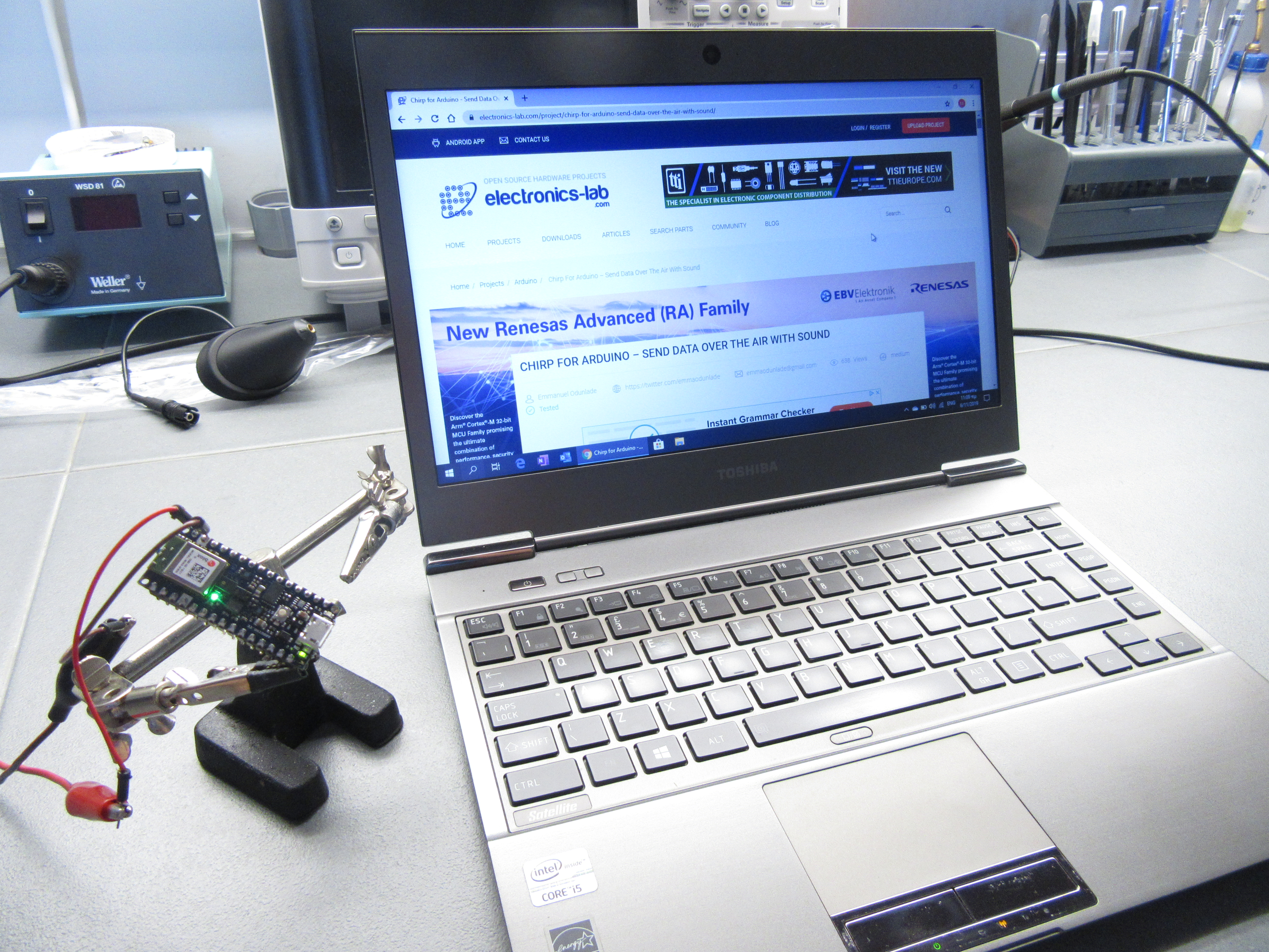
Instead of these prerecorded sounds provided by Chirp, you can decide to build another project which in place of the mic, will come with a speaker to broadcast the commands, so today’s project serves as the receiver. You can also develop your own sound command following the Audio API or play a random chirp from the applications page on the developers website.
Demo Video
Data over sound is one of the hottest research topics currently due to the possibilities it holds around redefining the way devices communicate. With breakthroughs like Chirp’s Ultrasonic protocols (which will hopefully come to Arduino soon), devices will be able to communicate using non-audible sounds. This means commands could be embedded in songs without the “weird” bird sounds and so on.
That’s it for this tutorial guys. Do reach out to me via the comment section if you have any questions or are facing any challenges with this project.
Resources used for this project are from Chirp’s documentation on the usage with Arduino. You can check it out to learn more.


.png)


