Using Interrupts with Arduino
- Nick Koumaris
- http://educ8s.tv
- info@educ8s.tv
- 7.465 Views
- easy
- Tested
We can say that an Interrupt is an automatic transfer of software execution in response to a hardware event that is asynchronous with the current software execution. As it’s name says, interrupts, “interrupt” the normal program flow to perform an action (run another code block, function, etc.) and return back to the normal program flow when the action is completed. Interrupts can be established for events such as a counter’s number change, a pin changing state (from low to high or high to low), serial communication receiving information, or the Analog to Digital having established a conversion, etc., depending on what is supported by the microcontroller you are working with. For today’s tutorial, we will focus on interrupts as a result of pins changing state and how these can be used on the Arduino.
To monitor their digital pins for changes, microcontrollers by default use a technique generally referred to as “polling“, which means they constantly check the digital pins to know if any change has occurred. This usually takes a lot of the microcontroller’s resources and reduces its response time which may not be a problem in most applications but could be important in time-critical ones. One of the solutions usually adopted in scenarios where all the negatives of polling need to be eradicated is the use of external Interrupts. Interrupts provide the microcontrollers with a way of multitasking such that a particular digital pin does not need to be continually polled, as the pin would by itself signal the microcontroller and immediately pause the operations when a change occurs. Asides in time-critical applications, where the microcontroller needs increased response rate, Interrupts are widely used in power saving applications for all kind of device, from smartphones and their power button to your PC and the spacebar and the application goes on.
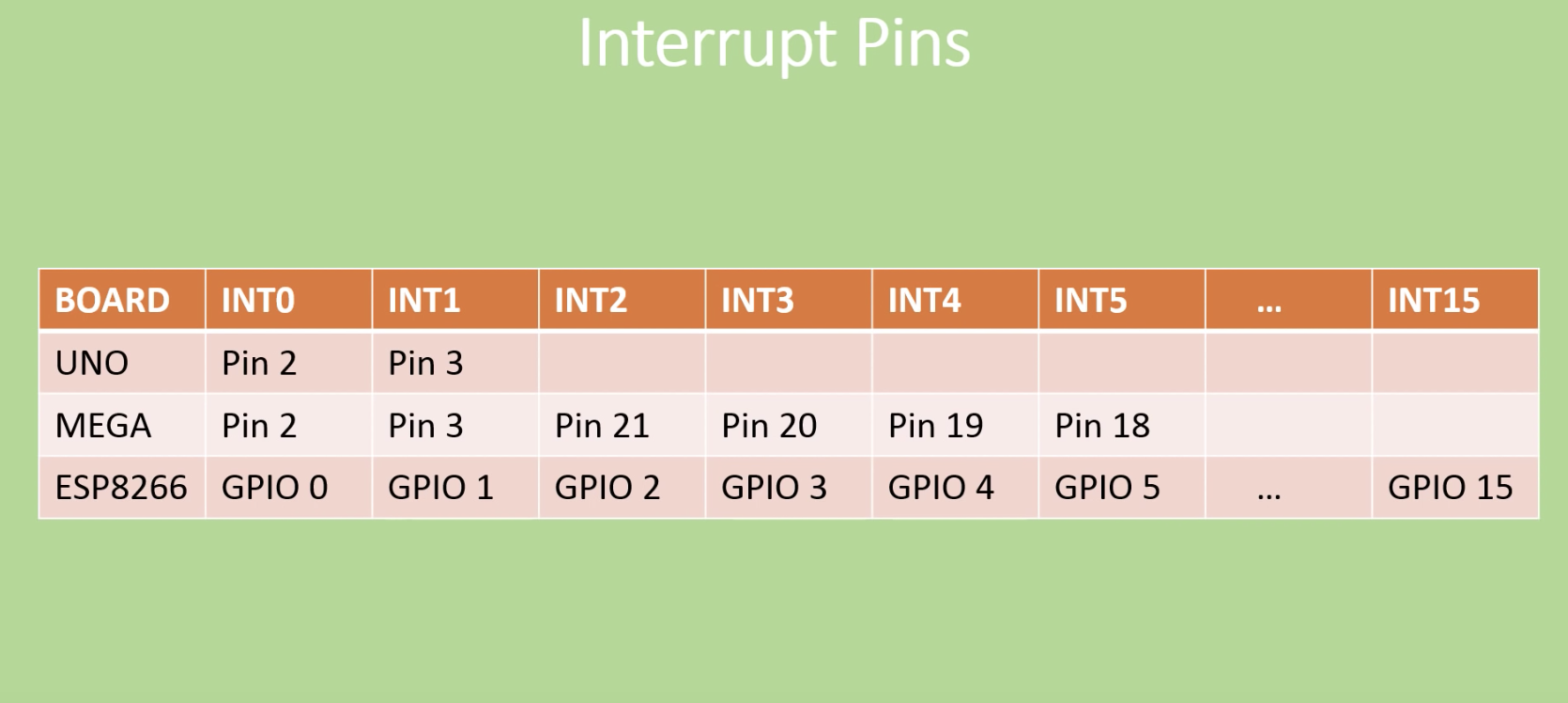
The number of external interrupts possessed by microcontrollers differs from one microcontroller to the other. For example, the Arduino boards, from UNO to Duemilanove, have only two interrupts which are located on digital pins 2 and 3. Other boards like the Arduino Mega has 6 while the esp8266 (ESP 12e) has about 16 interrupt pins.
For today’s tutorial, We will look at how the interrupt can be used in an Arduino project and as an example, we will connect a switch to one of the interrupt pins on the Arduino and use it to control a LED which is turned on/off when the interrupt is triggered.
Required Components
The following components are required to build today’s tutorial;
- Arduino Uno or Nano
- Buttons
- Small PIR sensor
- Small Breadboard
- LEDs
- Resistors
- Jumper Wires
- Wires
- Power Bank
As usual, the exact components used for this tutorial can be bought via the link attached to them.
Schematics
The schematics for this project is quite simple. We need to connect an LED and a pushbutton to the Arduino, in that way than when the pushButton is pressed, an interrupt is triggered on the Arduino to control the on/off state of the LED.
Connect the components as shown in the schematics below.
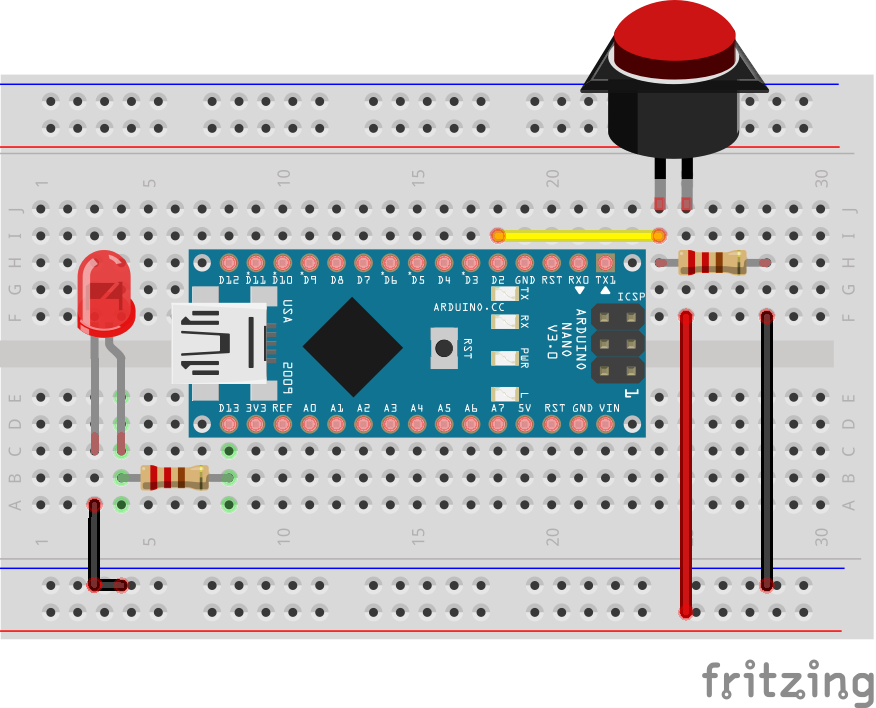
As mentioned initially, either of the Arduino Uno and the Nano can be used for this project as they all have the same pin configuration, the same number of interrupt pins and the interrupt is located on the same pin across the two boards.
Asides using the switch as the trigger, a PIR Motion sensor can also be used to trigger the interrupt when motion is detected. To use the PIR sensor, connect it to the Arduino as shown in the schematics below.
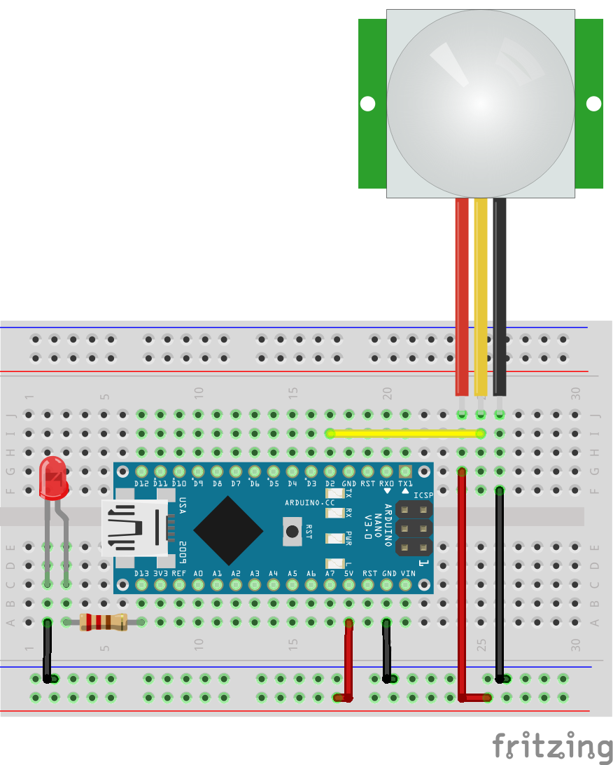
Since motion sensors behave like a switch, the same code can be used with the same schematics.
Code
The code for this project is quite easy. As mentioned at the beginning, our goal for today’s project is to learn how to perform an action (turn on/off and LED in this case) when an interrupt is triggered. Thus we will program the Arduino to watch out for a “rising edge” interrupt on the pin to which the button is connected and respond by turning the LED on.
To do a quick explanation of the code; We start by creating a boolean variable “ledon” to store the state of the LED. This helps the sketch remember the last state of the LED.
//Written by Nick Koumaris
//info@educ8s.tv

volatile boolean ledOn = false;
Next, we write the void setup() function. We start by declaring the pinMode of the pins to which the LED and the PushButtons are connected. With that done, we then call the attachinterrupt() function to provide the microcontroller with details of the interrupt operation. The attachinterrupt() function takes 3 arguments; The interrupt pin, the function to run when triggered, the type of trigger to look out for. The trigger could be either of “rising” (pin goes from low to high), “falling” (pin goes from high to low) or “either” (either of the two).
void setup() {
  pinMode(13,OUTPUT);
  pinMode(2,INPUT);
  attachInterrupt(0,buttonPressed,RISING);
}
Since we won’t be repeating any action, we will leave the void loop() section blank. Thus, up next is the buttonpressed() function. This function is called when a rising edge signal triggers the interrupt. The function simply changes the state of the LED, turning it OFF if it was ON and turning it ON if it was OFF.
void loop() {

}

void buttonPressed()
{
  if(ledOn)
  {
    ledOn = false;
    digitalWrite(13,LOW);
  }else
  {
    ledOn = true;
    digitalWrite(13,HIGH);
  }
}
The complete code for the project is available below and attached under the download section.
//Written by Nick Koumaris
//info@educ8s.tv

volatile boolean ledOn = false;

void setup() {
  pinMode(13,OUTPUT);
  pinMode(2,INPUT);
  attachInterrupt(0,buttonPressed,RISING);
}

void loop() {

}

void buttonPressed()
{
  if(ledOn)
  {
    ledOn = false;
    digitalWrite(13,LOW);
  }else
  {
    ledOn = true;
    digitalWrite(13,HIGH);
  }
}
Demo
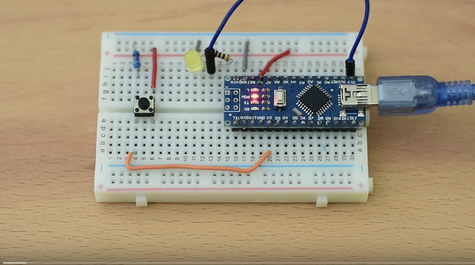
Go over the schematics once again to ensure everything is connected as it should then connect your Arduino to the computer and upload the code to it. You can now press the push button to see the LED respond.
Final thoughts
Interrupts are used for a plethora of applications including; implementing low power algorithms, eradicating polling to preserve system resources, and to ensure quick response in time-critical applications like alarm systems.
That’s it for today’s project. Thank you for reading. Do reach out via the comment section if you have any question or comments.
The video version of this tutorial is available on Youtube.


.png)


