AMP – Arachnoid Mobile Platform
- Tsirogiannis Andreas
- andrewsweet4@hotmail.com
- 18.294 Views
- moderate
- Non tested
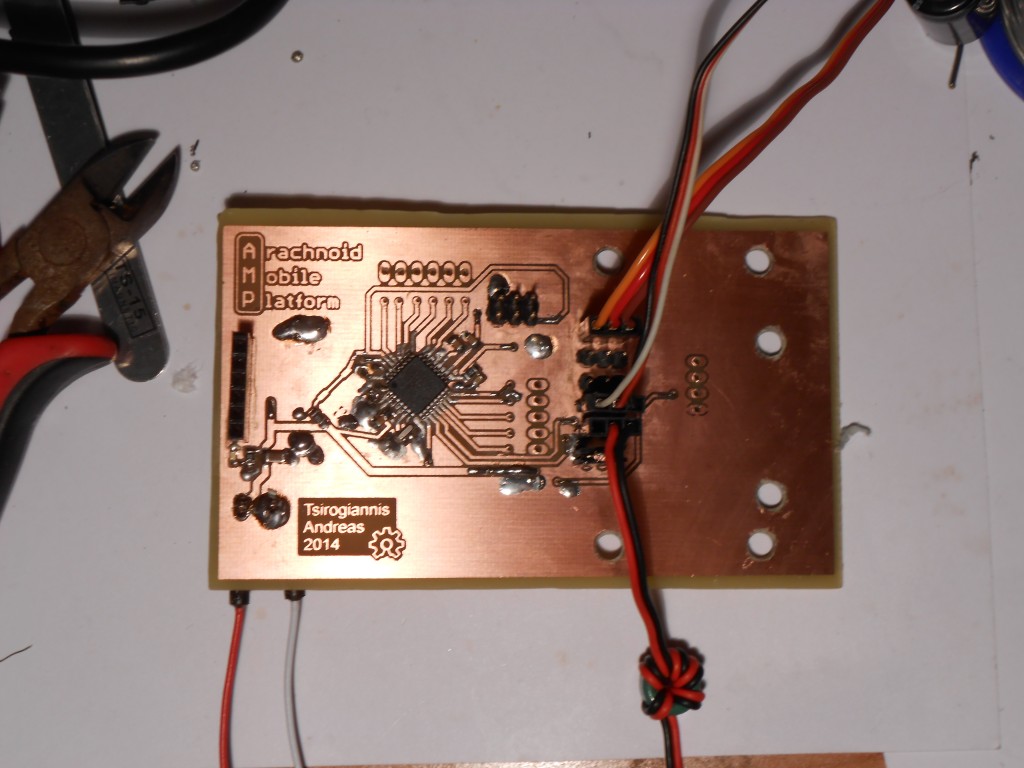
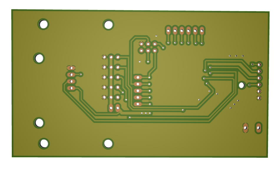
The Arachnoid Mobile Platform is an open source robotics development platform used to make small autonomous moving robots. It can be either configured as a four-legged robot, or as a two wheeled robot. The PCB board holds all the electronics and mechanical components, and also serves as the chassis of the robot.
Project Status: Current build is rev 1.1 assembled 8/2/2014
Description
The Brains
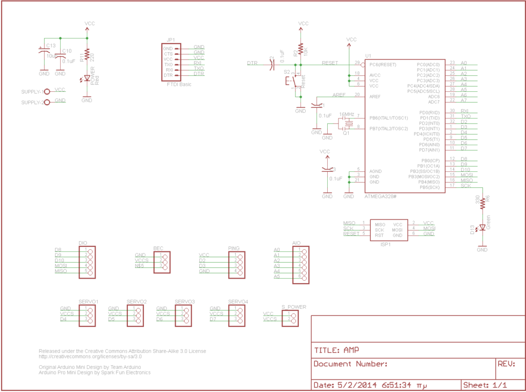
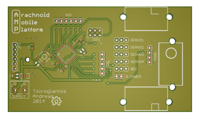
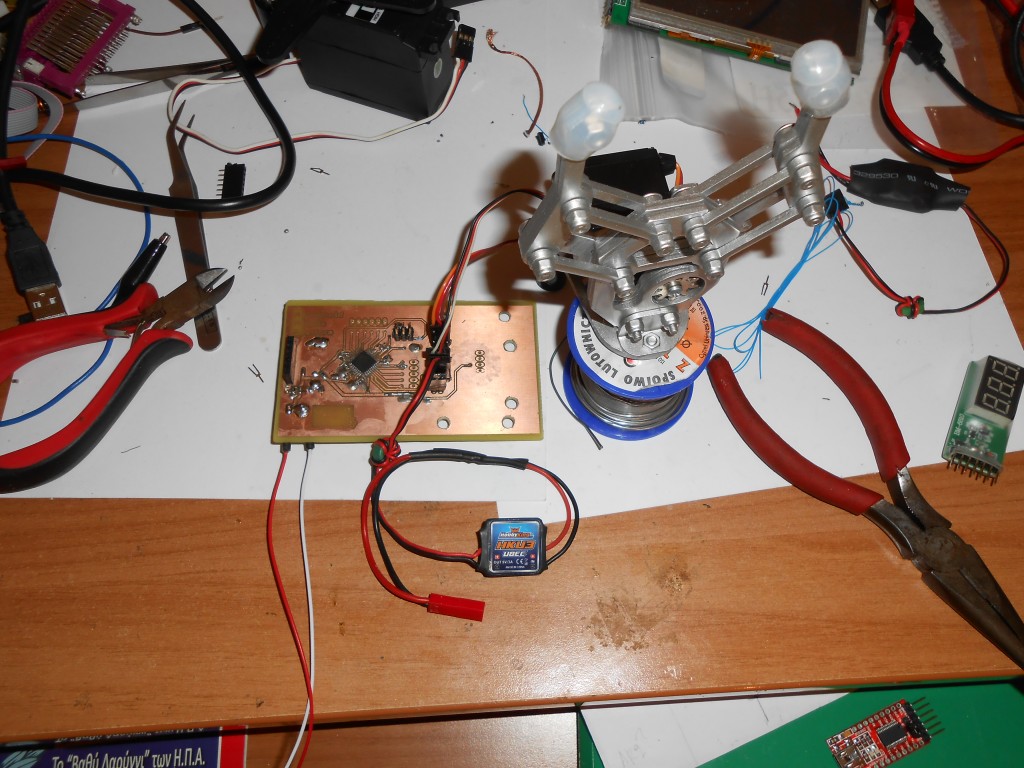
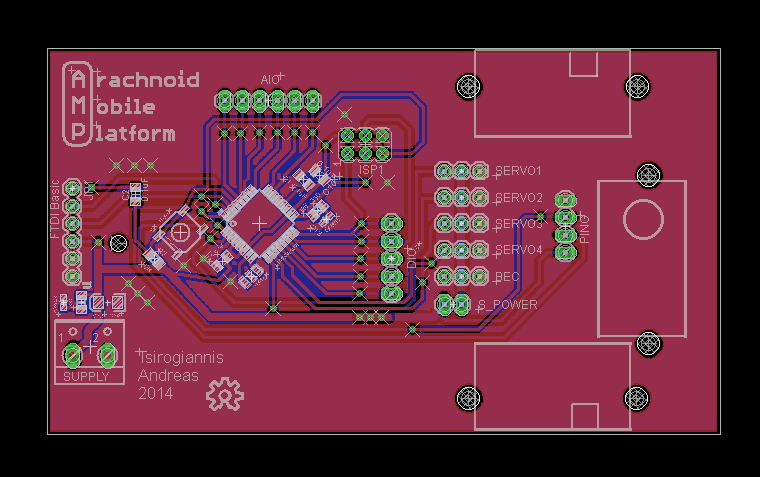
The whole project is based on an ATmega328-AU (The SMD version of the infamous ATmega328) and is flashed with the standand Arduino pro mini bootloader. Consequently, the board can be easily programmed using the Arduino IDE platform. As for the programming hardware, there are two interfaces for the user to upload his/her code. There is an FTDI headerwith the standard pinout (on the leftmost side of the board marked “FTDI master”), and an ISP header (marked as “ISP”) for using with a compatible Atmel SPI programmer. The tool used here for uploading the code to the board is a classic FTDI FT232 USB to serial interface board. The microcontroller runs on 5V DC.
Movement
The robot uses 2 continous rotation servos for its movement when configured as a wheeled robot, and three continous rotation servos when configured as a four-legged robot. Aditionally another is used for panning the ultrasonic PING sensor for obstacle avoidance mentioned below. All the servos used in this examle are HXT900 9g servos, from hobbyking.com. Any standard 9g micro servo should be fine for this project (provided it is bought/modified as continous rotation for the drivetrain).
Headers and sensors
The board contains 4 headers for direct servo connection (marked as “Servo 1 through 4”) on the board as well as as an ultrasonic HC-SR04 sensor direct interface (marked as “PING”). The ultrasound sensor mounts on the center servo which allows it to turn in a 30-50 degree radious in order to “scan” its surroundings and find the path with the least obstacles in place. Additionally, all the remaining digital and analog I/O pins, are brought to their respective headers for future expansion (Digital I/O is brought to the “DIO” header and analog IO is brought to the “AIO” header).
Power
A single 5V power source is necessary to run the entire board. The supply voltage can be provided either to the screw terminals directly, or through the “BEC” header, using a standard hobby UBEC (the name comes from “battery ellimination circuit”, just a fancy name for a 2-3 cell lipo battery to 5volt regutator). The one i found luck with is the cheap and marvelous 5V/3A that hobbyking sells (www.hobbyking.com). Beneath the BEC header there is a two pin jumper that isolates the servo and the microcontroller supply. It can be used for either powering the servos from a different heavy-duty power source or disconnecting the servo load from the micro in order to flash it with new firmware.
Software
The software is currently in developing stage and is going to be public available when finished. Feel free to write your own code and upload it to electronics-lab.com.


.png)


hammouda