2 Digit 99 Seconds Timer
- Rajkumar Sharma
- 22.968 Views
- medium
- Tested
- SKU: EL46820
- Quote Now
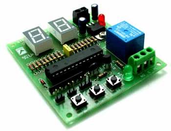
2 Digit Count Down Timer is a utility Count Down timer project for upto 99 seconds of countdown time. This project can find many uses in your shack and home. The relay output remains on during the Count Down period, allowing you to interface load or alarm that you want to keep it on for a certain amount of time (in seconds).
Specifications
- Microcontroller based design for greater accuracy and control
- Power supply input 12 VDC 200 mA
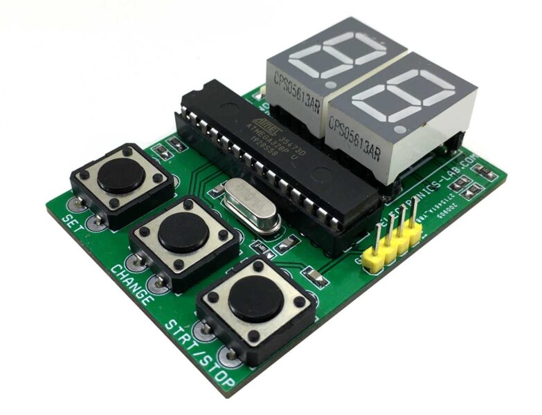
- Two 0.5″ display segments to display time
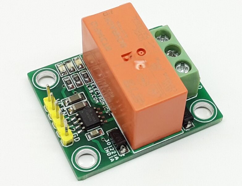
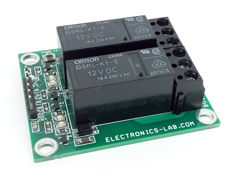
- 12V SPDT (Single Pole Double Throw) relay for alarm use
- Single key start and dual key alarm time set function
- Power and Relay-On LED indicator
- Terminal connectors for connecting power supply input and relay output to the PCB
- Onboard regulator for regulated supply to the kit
- Crystal resonator based design for better accuracy
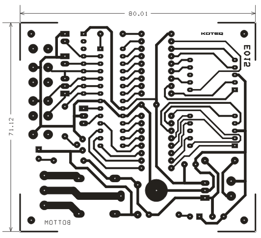
- PCB dimensions 72 mm x 81 mm
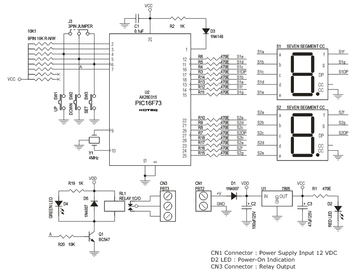
This is a microcontroller based 2 Digit (99 Seconds) Count Down Timer. This Count Down Timer is very easy to use and easy to configure. This project can find a lot of application areas where you need a device to remain ON (or OFF) for a certain period of time (upto 99 Seconds). Power to the circuit is applied at CN1 (12 VDC). D1 provides the reverse polarity protection to this kit. LED D2 confirms DC Power Supply to the board. S1 and S2 displays Count Down time. J3 provide an easy way of connecting external switches to this board. LED D4 confirms the relay status.
Operating Instructions:
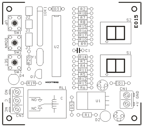
The setting up of countdown period and START Function for this kit is accomplished with the help of 3 tactile switches shown as SW1, SW2 and SW3 in the schematic and labeled as UP, DOWN and SET on the PCB respectively.
- Setting Time : The default value is shown on display S1 and S2 respectively. You can change this value by simply pressing the UP and DOWN key.
- Start : You can start the Count Down by pressing SET key. When the Count Down starts the relay is energized, indicated with the glow of LED D4. Once the Display (S1 and S2) reaches 0 the relay is de energized.


.png)


we want 99 min timer
You may refer to this projects for longer duration timer: https://www.electronics-lab.com/project/simple-timer-with-pic16f628a/
operating instruction, can step 2 be relay de energized when count down start and how
The relay is ON during the count down, so you can use NC (normal connected) or NO (normal open) connection of the relay, according to your needs.
thank you for the reply.i need time delay by using count down counter. relay will be off before starting count down then on. can i get asm file to make some change.best regards
We are sorry, .asm code isn’t available at this moment.
Sir I made this circuit as per circuit diagram but it is not working properly not showing display properly so I need ur help to solve this problem
Make sure you have wired the circuit as shown in schematic and verify your PIC is programmed and running.
can this module be used to drive 8″led digits?
7-Segment displays are directly driven from MCU pins. Current output on these pins is limited to 20-40mA, so to drive larger displays you will need some additional circuitry using transistors to control the segments.
do this PIC16F73 is preprogrammed or it need to be programmed for this purpose
Need to be programmed with the hex file provided in downloads on this page.
i have the same problem as Rafiq : i built the timer, it seems to be working but the display has the segments somehow scrambled .
can someone please help me ?
Turns out the markings on the circuit schematics regarding the connections between the PIC and the led disply are wrong ; the correct connexions are :
-segment E1 on pin 25
-segment D1 on pin 24
-segment C1 on pin 23
-DP1 on pin 28
-segment B1 on pin 22
-segment A1 on pin 21
-segment F1 on pin 26
-segment G1 on pin 27
-segment E2 on pin 15
-segment D2 on pin 14
-segment C2 on pin 13
-DP2 on pin 18
-segment B2 on pin 12
-segment A2 on pin 11
-segment F2 on pin 16
-segment G2 on pin 17
The presented PCB is probably correct and will work but if you modify the PCB as i did then keep in mind the above modifications .
PS: it would have been much easier to modify the firmware then it was ,in my case,to modify de PCB so it would be much appreciated to post the firmware too .