

Sound to Colour Light Effects – Arduino Compatible
- Rajkumar Sharma
- 1.213 Views
- moderate
- Tested
- SKU: EL111627
- Quote Now

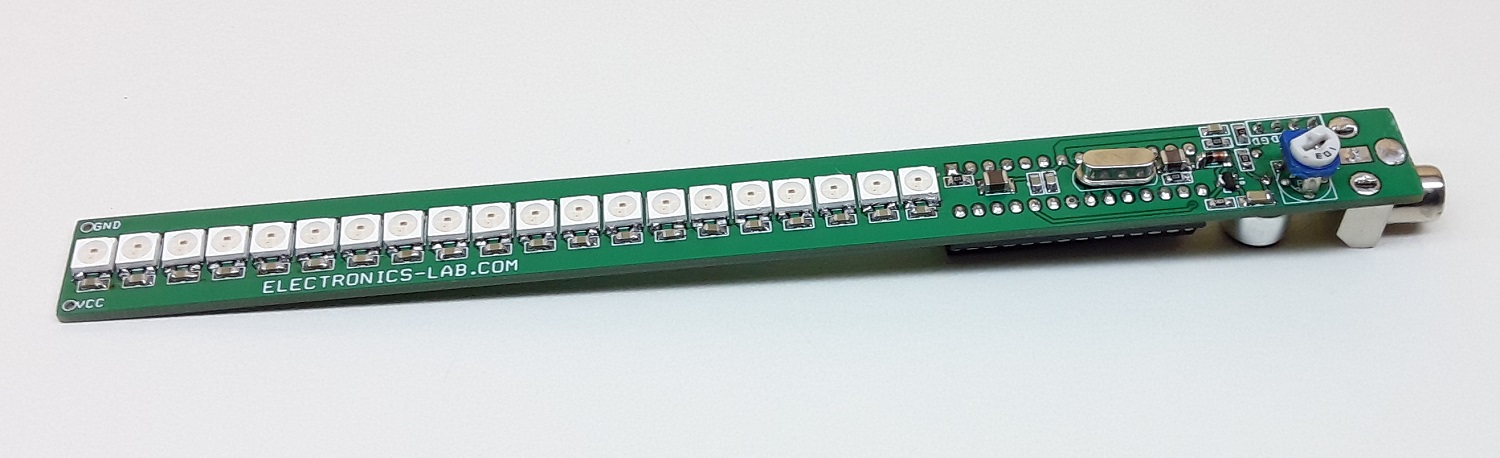
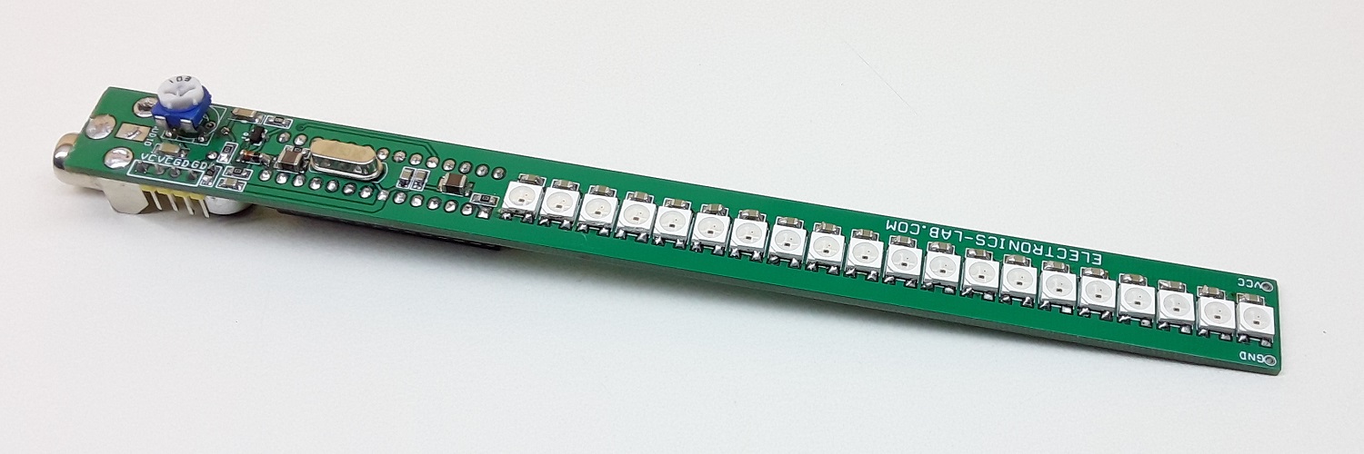
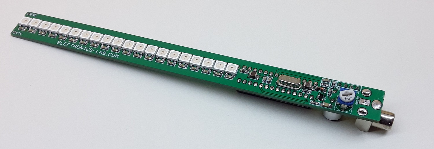
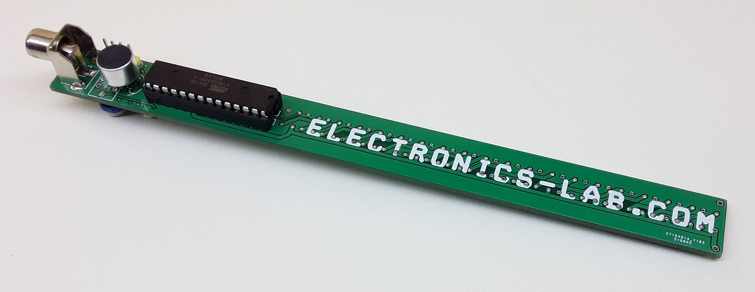
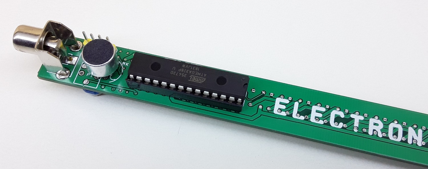
This is a fun-loving project based on the Arduino platform. The project creates color light effects with sound level sense by an onboard condenser microphone. The project consists 20 x WS2812B RGB LEDs, an Atmega328 micro-controller, condenser microphone along with pre-amplifier, RCA connector, and trimmer potentiometer to direct feed audio. The project can be used in fun parties, disco parties etc. Just power the board and RGB LEDs will create different colors as per sound level. Board has the option of direct audio input or sound sense by the microphone, users may change the Arduino example code as per requirement or write their own code.
The default Arduino code works with the microphone as the sound sensor. The project also works with direct audio signal input. In this case use RCA connector J1 to feed the audio, trimmer potentiometer PR1 provided to adjust the audio input signal level. The input audio signal should not be more than 4Vpp (peak to peak.). The audio signal is connected to A1 analog pin of Arduino. Since the project is Arduino compatible, many applications such as sound to light effects, audio to light effects, VU meter, sound level meter are possible with this board.
Arduino Code
Arduino example code is available as a download. A new Atmega328 chip requires, Bootloader and Arduino code, follow the links below to learn more about programming the chip.
- https://www.electronics-lab.com/project/installing-the-arduino-bootloader-on-the-atmega328p-microcontroller/
- https://www.arduino.cc/en/Tutorial/BuiltInExamples/ArduinoToBreadboard
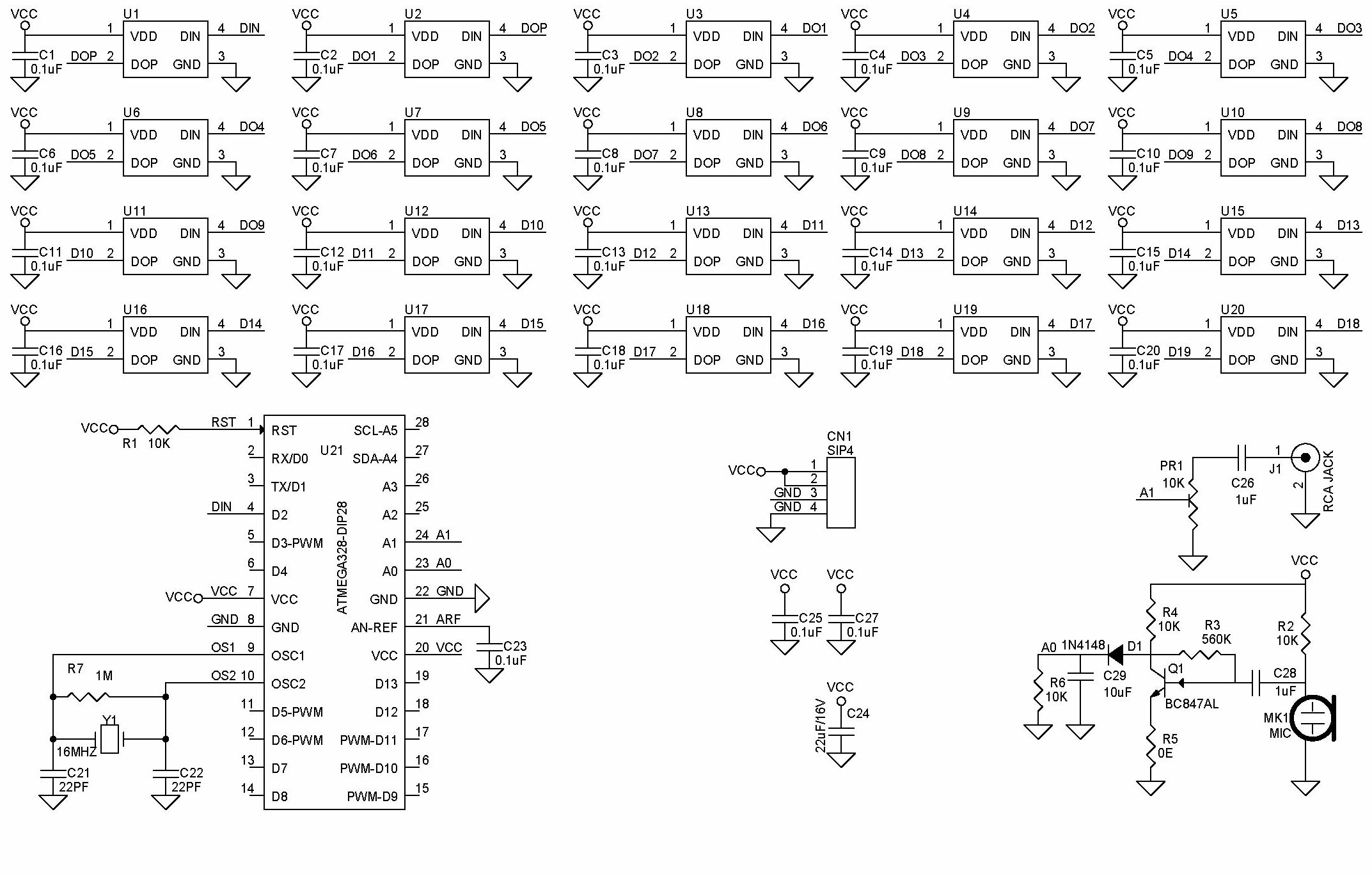
Arduino Pin Configuration
Digital pin D2 is connected to WS2812B LED, Analog pin A0 to Microphone, Analog pin A1 direct audio signal input.
Applications
- Sound to Light Effects
- Audio Signal to Light Effects
- Sound Level Meter
- Audio VU Meter
Features
- Supply 5V DC @ 250mA when all LEDs are ON
- Detect Sound using on Board Microphone
- Direct Audio Signal Input RCA Connector
- PCB Dimensions 179.71 x 16.51 mm
Schematic
Parts List
| NO | QNTY. | REF | DESC. | MANUFACTURER | SUPPLIER | SUPPLIER PART NO |
|---|---|---|---|---|---|---|
| 1 | 1 | CN1 | 4 PIN MALE HEADER PITCH 2.54MM | WURTH | DIGIKEY | 732-5317-ND |
| 2 | 23 | C1 to C20 + C23,C25,C27 | 0.1uF/50V SMD SIZE 0805 | MURATA/YAGEO | DIGIKEY | |
| 3 | 2 | C21,C22 | 22PF/50V SMD SIZE 0805 | MURATA/YAGEO | DIGIKEY | |
| 4 | 1 | C24 | 22uF/16V SMD SIZE 1210 | TDK | DIGIKEY | 445-1436-1-ND |
| 5 | 2 | C26,C28 | 1uF/25V SMD SIZE 1206 | MURATA/YAGEO | DIGIKEY | |
| 6 | 1 | C29 | 10uF/16V SMD 1206 OR 1210 | MURATA/YAGEO | DIGIKEY | |
| 7 | 1 | D1 | 1N4148 | MICROCHIP | DIGIKEY | 1N4148UR-1-ND |
| 8 | 1 | J1 | RCA JACK | CUI DEVICES | DIGIKEY | CP-1459-2-ND |
| 9 | 1 | MK1 | MIC | CUI DEVICES | DIGIKEY | 102-1721-ND |
| 10 | 5 | R1,PR1,R2,R4,R6 | 10K 5% SMD SIZE 0805 | |||
| 11 | 1 | Q1 | BC847AL | ON SEMI | DIGIKEY | 2156-BC847ALT1G-OS-ND |
| 12 | 1 | R3 | 560K 5% SMD SIZE 0805 | DIGIKEY | ||
| 13 | 1 | R5 | 0E | DIGIKEY | ||
| 14 | 1 | R7 | 1M 5% SMD SIZE 0805 | DIGIKEY | ||
| 15 | 20 | U1 to U20 | WS2812B | SPARKFUN | DIGIKEY | 1568-COM-16347CT-ND |
| 16 | 1 | U21 | ATMEGA328-DIP28 | MICROCHIP | DIGIKEY | ATMEGA328-PU-ND |
| 17 | 1 | Y1 | 16MHZ | ECS INC | DIGIKEY | X1103-ND |
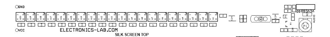
Connections
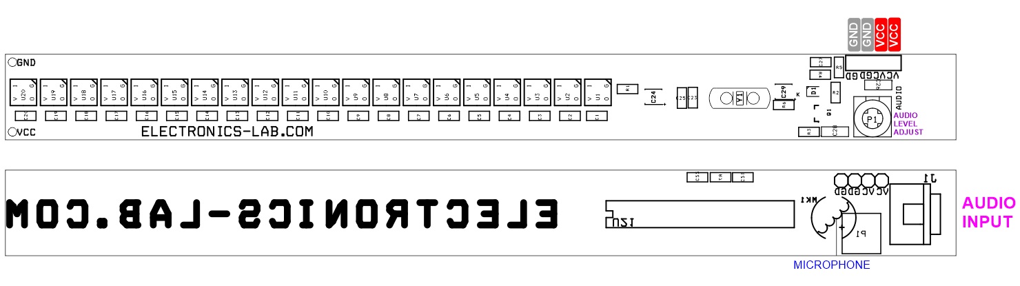
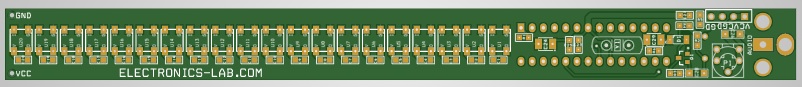
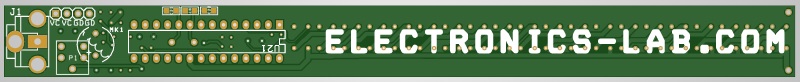
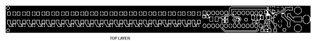
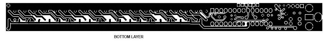
Gerber View
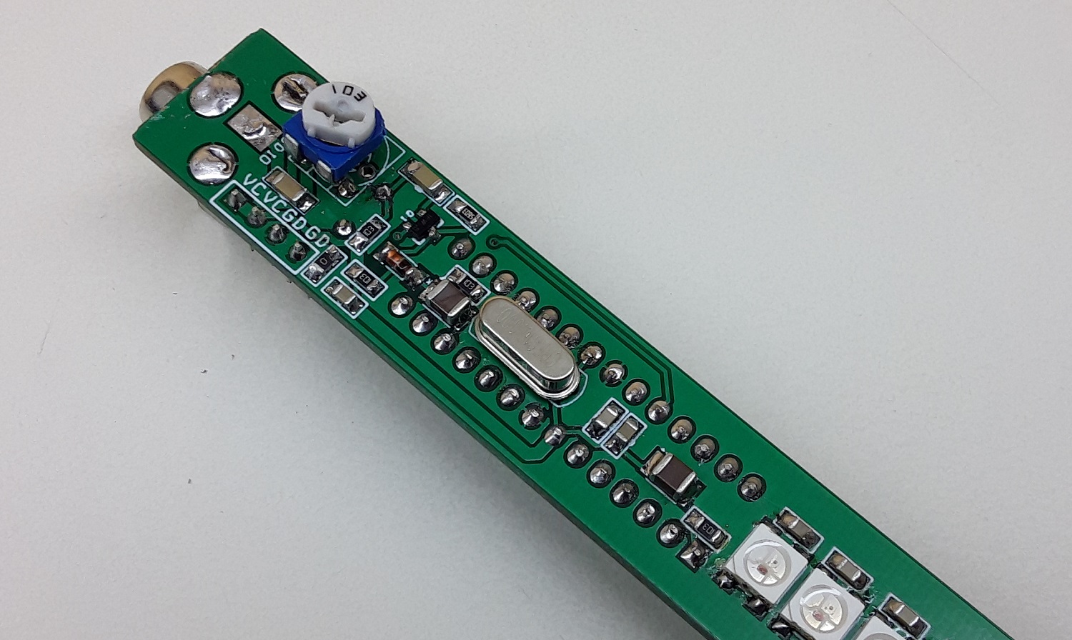
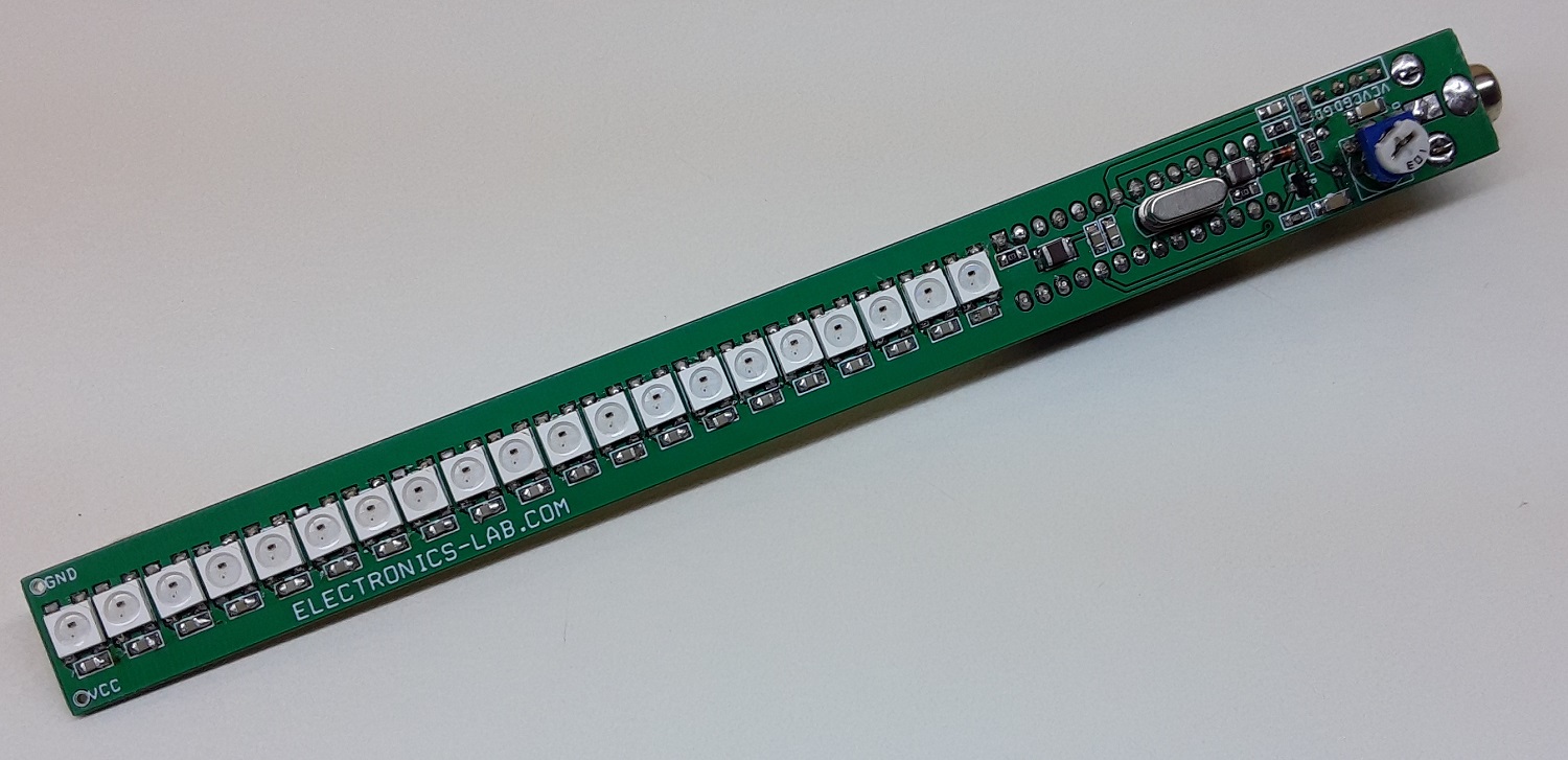
Photos
Video
WS2812B Datasheet
PCB
.png)


Hi there!
I’m a bit confused to connecting pin 2 in first WS2812B(U1) to next one(U2)or to micro, so at the beginning i linked pin 2nd of U1 to micro my mean its PD2_(PCINT18/INT0) to pin 2(DOP) in U1,am i corrected on it ?!
i putted pin 4 of first WS2812B(U1) to pin 2 of the second WS2812B(U2)
and the same for the next .
another point is with U20 what we should do with pin 4 how and where it should connect ?.
its my first project that i decided to build and design on Proteus .
thanks