Automatic LED Stairway Lighting – Arduino Compatible
- Rajkumar Sharma
- 3.520 Views
- medium
- Tested
- SKU: EL109127
- Quote Now
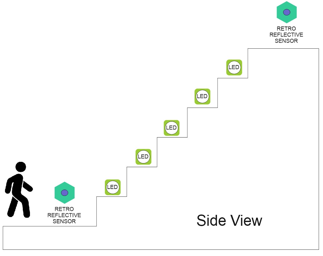
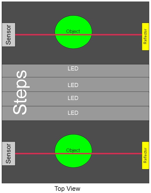
This creative idea is suitable for a stairway with 16 stairs, each stair can have a 12V LED. It has two sensors one at the start and one at the end of the stairs and when the sensor trigered at any end it starts a process of lighting each of the steps in a progressive cycle starts. When you reach the other side of the stairway and the second sensor is triggered it will start to extinguish all the lit lights in the ascending cycle.
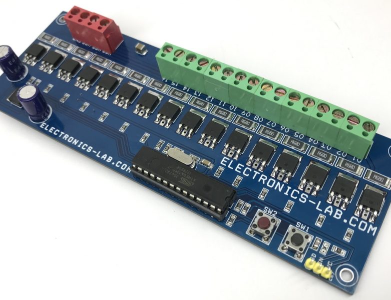
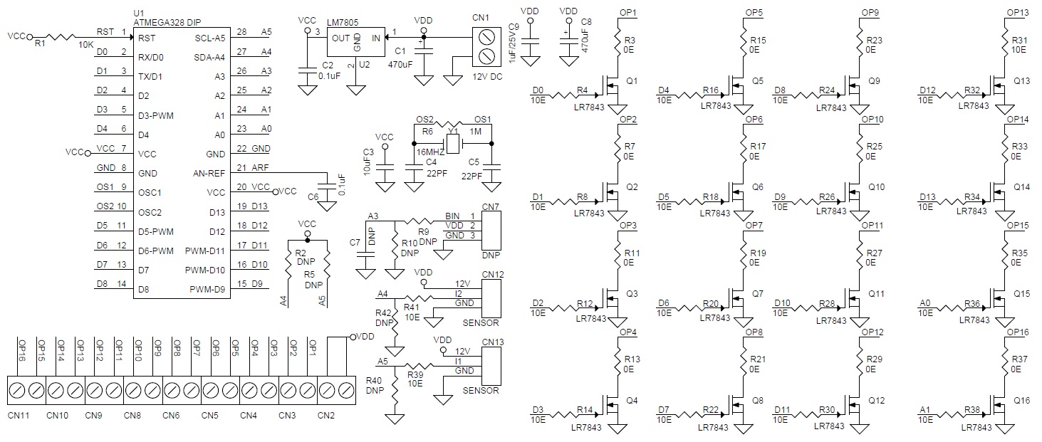
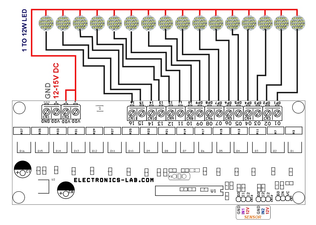
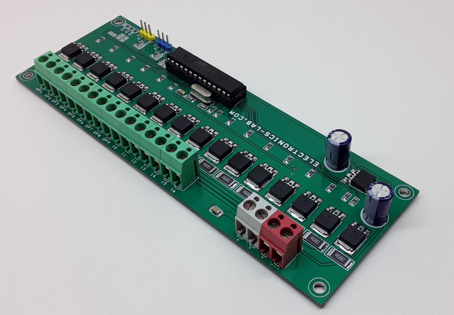
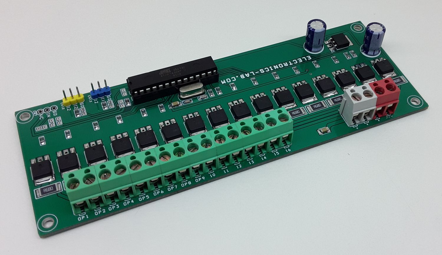
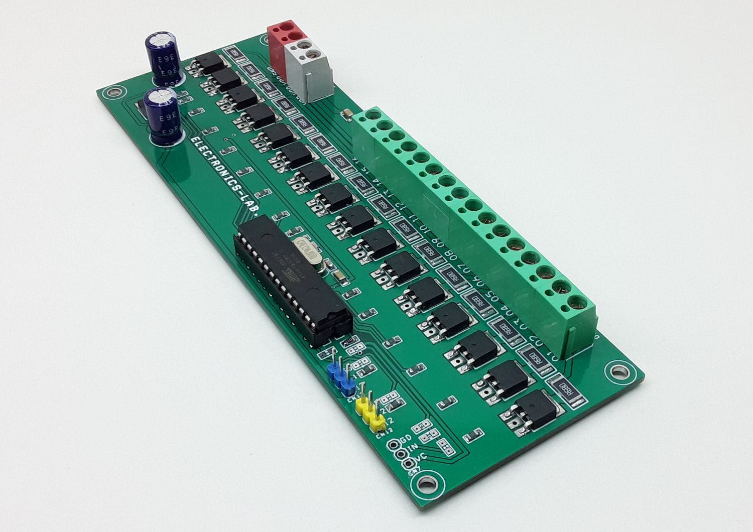
This is a very simple and easy to build project based on the Arduino platform The board consists of an ATMEGA328 microcontroller, 16 channel MOSFETs, 2 optical retro-reflective or optical defuse sensor, 16 x 12V LEDs, LM7805 regulator, DC filter capacitors, and optional current limiting resistor on each MOSFET. The circuit requires 12V DC, each MOSFET can drive a LED up to 1A (0.5 to 12W LED)
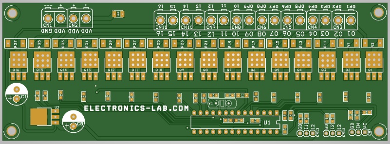
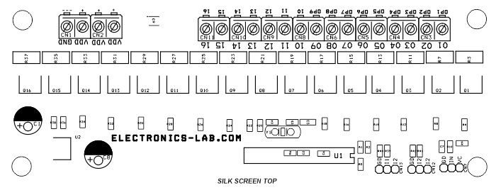
LEDs: Each MOSFET can drive LED of 0.5W to 12W, it is advisable to use 12V LEDs, use appropriate current limiting resistors (R3, R15, R23, R31, R7, R17, R25, R33, R11, R19, R27, R35, R13, R21, R29, R37) if lower voltage LEDs is used. The default value for these resistors is 0 Ohms.
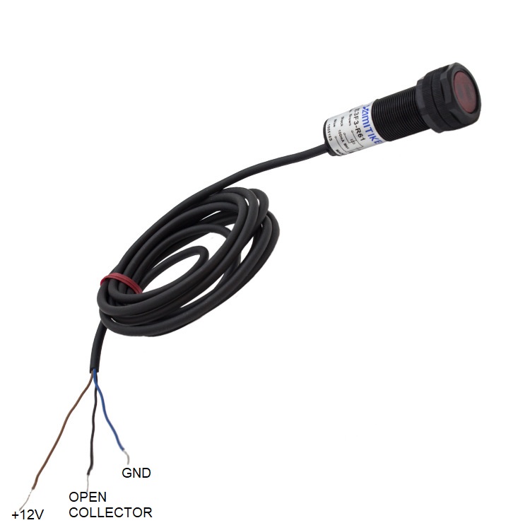
Sensor: Optical Retro-reflective sensor or optical defuse sensor can be used. The project is tested with a reflective sensor from Omron, NPN type sensor is best suitable. The optical sensor has a supply range of 12V to 24V DC which is within the supply range to interface with this project. Retroreflective sensor E3F3-R11 from Omron is suitable, it has 3 meters range with an open collector NPN type. Defuse sensor E3F3-D12 can also be used if it used in a narrow range.
Stairway: Circuit can drive 16 channels, for more steps, use multiple LEDs in parallel configuration considering load should not exceed 1A on each channel.
Cooling: It is advisable to use forced air to cool down the MOSFETs if full load 1A on each channel is used, load up to 0.5A on each channel doesn’t require a fan.
Arduino Code
Arduino example code is provided as a download. This code can be modified as per user requirements, delay between LED ON/OFF can be changed in code. Follow the link below to learn programming the new ATMEGA328 microcontroller using Arduino IDE.
https://www.arduino.cc/en/Tutorial/BuiltInExamples/ArduinoToBreadboard
Features
- Operating Supply 12V DC
- 16 Channels x 12V LEDs
- Load up to 1A x 16 Channel
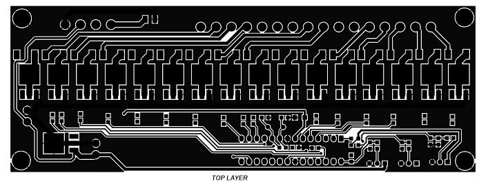
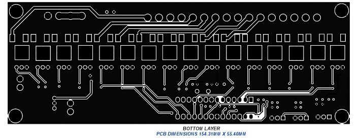
- PCB Dimensions 154.31 x 55.40mm
Schematic
Parts List
| SR | QNTY. | REF. | DESC. | MANUFACTURER | SUPPLIER | SUPPLIER PART NO |
|---|---|---|---|---|---|---|
| 1 | 1 | CN1 | 2 PIN SCREW TERMINAL 5.08MM PITCH | PHOENIX | DIGIKEY | 277-1247-ND |
| 2 | 9 | CN2 to CN11 | 2 PIN SCREW TERMINAL 5.08MM PITCH | PHOENIX | DIGIKEY | 277-1247-ND |
| 2 | R2,R5,CN7,C7,R9 | DNP | DIGIKEY | OMIT | ||
| 3 | 8 | R10,R40,R42 | DNP | DIGIKEY | OMIT | |
| 4 | 2 | CN12,CN13 | 3 PIN MALE HEADER 2.54MM PITCH | WURTH | DIGIKEY | 732-5316-ND |
| 5 | 2 | C1,C8 | 470uF/25 ELECTROLYTIC | RUBYCON | DIGIKEY | 1189-1869-ND |
| 6 | 3 | C2,C6 | 0.1uF/50V SMD SIZE 0805 | MURATA/YAGEO | DIGIKEY | |
| 7 | 1 | C3 | 10uF/10V SMD SIZE 1206 | MURATA/YAGEO | DIGIKEY | |
| 8 | 2 | C4,C5 | 22PF/50V SMD SIZE 0805 | MURATA/YAGEO | DIGIKEY | |
| 9 | 16 | Q1 to Q16 | IRLR7843 | INFINION | DIGIKEY | 448-IRLR7843TRLPBFCT-ND |
| 10 | 1 | R1 | 10K 5% SMD SIZE 0805 | MURATA/YAGEO | DIGIKEY | |
| 10 | R3,R7,R11,R13,R15 | 0E SMD SIZE 2512 | BOURNS | DIGIKEY | CR2512-J/-000ELFCT-ND | |
| 10 | R17,R19,R21,R23,R25 | 0E SMD SIZE 2512 | BOURNS | DIGIKEY | CR2512-J/-000ELFCT-ND | |
| 11 | 15 | R27,R29,R33,R35,R37 | 0E SMD SIZE 2512 | BOURNS | DIGIKEY | CR2512-J/-000ELFCT-ND |
| 11 | R4,R8,R12,R14,R16,R18 | 10E 5% SMD SIZE 0805 | MURATA/YAGEO | DIGIKEY | ||
| 11 | R20,R22,R24,R26,R28,R30 | 10E 5% SMD SIZE 0805 | MURATA/YAGEO | DIGIKEY | ||
| 12 | 19 | R31,R32,R34,R36,R38,R39,R41 | 10E 5% SMD SIZE 0805 | MURATA/YAGEO | DIGIKEY | |
| 13 | 1 | R6 | 1M 5% SMD SIZE 0805 | MURATA/YAGEO | DIGIKEY | |
| 14 | 1 | U1 | ATMEGA328 DIP | MICROCHIP | DIGIKEY | ATMEGA328P-PU-ND |
| 15 | 1 | U2 | LM7805 | ONSEMI | DIGIKEY | MC78M05CDTGOS-ND |
| 16 | 1 | Y1 | 16MHZ | ECS INC. | DIGIKEY | X1103-ND |
| 17 | 1 | C9 | 1uF/25V | TDK | DIGIKEY | 445-5914-1-ND |
Connections
Sensor
Installation
Sensor Placement
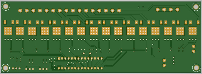
Gerber View
Code
/*
Modified code, Original Author, Monkfish's LED stair lights
*/

  //LED pin assignments
  int led1 = 0;
  int led2 = 1;
  int led3 = 2;
  int led4 = 3;
  int led5 = 4;
  int led6 = 5;
  int led7 = 6;
  int led8 = 7;
  int led9 = 8;
  int led10 = 9;
  int led11 = 10;
  int led12 = 11;
  int led13 = 12;
  int led14 = 13;
  int led15 = A0;
  int led16 = A1;

  // button pin assignments
  int b_up = A4; //button at bottom of stairs
  int b_down = A5; //button at top of stairs

  //LED delay settings
  int tOn = 400; //LED On delay
  int tOff = 750; //LED Off delay
  int del = 0; //Delay after action (used for debugging - set to 500-1000 to introduce a delay between each action)

  //variables
  static unsigned activeup = 0; //whether the system is active going upwards
  static unsigned activedown = 0; //whether the system is active going downwards

void setup() { //make with the setups

  //Set LED pins as output
  pinMode(led1, OUTPUT);
  pinMode(led2, OUTPUT);
  pinMode(led3, OUTPUT);
  pinMode(led4, OUTPUT);
  pinMode(led5, OUTPUT);
  pinMode(led6, OUTPUT);
  pinMode(led7, OUTPUT);
  pinMode(led8, OUTPUT);
  pinMode(led9, OUTPUT);
  pinMode(led10, OUTPUT);
  pinMode(led11, OUTPUT);
  pinMode(led12, OUTPUT);
  pinMode(led13, OUTPUT);
  pinMode(led14, OUTPUT);
  pinMode(led15, OUTPUT);
  pinMode(led16, OUTPUT);

  //Set button pins as input
  pinMode(b_up, INPUT_PULLUP);
  pinMode(b_down, INPUT_PULLUP);

  //Clear variables
  int activedown = 0;
  int activeup = 0;
}

void loop() {  //forever in your loopings

      //Set variables based on pin state
      int up = digitalRead(b_up);
      int down = digitalRead(b_down);

  if (up == LOW){ //Bottom button pressed


      //Set variables

          if (activeup == 1 || activedown == 1){ //checks if system active

                //If active

                OffDown(); //function call

          } else {

            //if not active

            delay(del);

            OnUp(); //function call

          }


  }

  if (down == LOW){

      if (activeup == 1 || activedown == 1){


                OffUp(); //function call

          } else  {


            OnDown(); //function call

          }

  }


}

void OnUp(){ //Switches lights on going up


               //set LEDs on in turn
               digitalWrite(led1, HIGH);
               delay(tOn);
               digitalWrite(led2, HIGH);
               delay(tOn);
               digitalWrite(led3, HIGH);
               delay(tOn);
               digitalWrite(led4, HIGH);
               delay(tOn);
               digitalWrite(led5, HIGH);
               delay(tOn);
               digitalWrite(led6, HIGH);
               delay(tOn);
               digitalWrite(led7, HIGH);
               delay(tOn);
               digitalWrite(led8, HIGH);
               delay(tOn);
               digitalWrite(led9, HIGH);
               delay(tOn);
               digitalWrite(led10, HIGH);
               delay(tOn);
               digitalWrite(led11, HIGH);
               delay(tOn);
               digitalWrite(led12, HIGH);
               delay(tOn);
               digitalWrite(led13, HIGH);
               delay(tOn);
               digitalWrite(led14, HIGH);
               delay(tOn);
               digitalWrite(led15, HIGH);
               delay(tOn);
               digitalWrite(led16, HIGH);

               activeup = 1; //Set system as active up


} //end OnUp

void OffUp(){ //switches lights off going up


         //sets LEDs off in turn
         digitalWrite(led1, LOW);
         delay(tOff);
         digitalWrite(led2, LOW);
         delay(tOff);
         digitalWrite(led3, LOW);
         delay(tOff);
         digitalWrite(led4, LOW);
         delay(tOff);
         digitalWrite(led5, LOW);
         delay(tOff);
         digitalWrite(led6, LOW);
         delay(tOff);
         digitalWrite(led7, LOW);
         delay(tOff);
         digitalWrite(led8, LOW);
         delay(tOff);
         digitalWrite(led9, LOW);
         delay(tOff);
         digitalWrite(led10, LOW);
         delay(tOff);
         digitalWrite(led11, LOW);
         delay(tOff);
         digitalWrite(led12, LOW);
         delay(tOff);
         digitalWrite(led13, LOW);
         delay(tOff);
         digitalWrite(led14, LOW);
         delay(tOff);
         digitalWrite(led15, LOW);
         delay(tOff);
         digitalWrite(led16, LOW);

         //set system as being off
         activeup = 0;
         activedown = 0;


} //End OffUp

void OnDown(){ //switches lights on going down


         //set LEDs on in turn
         digitalWrite(led16, HIGH);
         delay(tOn);
         digitalWrite(led15, HIGH);
         delay(tOn);
         digitalWrite(led14, HIGH);
         delay(tOn);
         digitalWrite(led13, HIGH);
         delay(tOn);
         digitalWrite(led12, HIGH);
         delay(tOn);
         digitalWrite(led11, HIGH);
         delay(tOn);
         digitalWrite(led10, HIGH);
         delay(tOn);
         digitalWrite(led9, HIGH);
         delay(tOn);
         digitalWrite(led8, HIGH);
         delay(tOn);
         digitalWrite(led7, HIGH);
         delay(tOn);
         digitalWrite(led6, HIGH);
         delay(tOn);
         digitalWrite(led5, HIGH);
         delay(tOn);
         digitalWrite(led4, HIGH);
         delay(tOn);
         digitalWrite(led3, HIGH);
         delay(tOn);
         digitalWrite(led2, HIGH);
         delay(tOn);
         digitalWrite(led1, HIGH);

         activedown = 1; //sets system as active down


} //End OnDown

void OffDown(){ //switches lights off going down

       //sets LEDs off in turn
       digitalWrite(led16, LOW);
       delay(tOff);
       digitalWrite(led15, LOW);
       delay(tOff);
       digitalWrite(led14, LOW);
       delay(tOff);
       digitalWrite(led13, LOW);
       delay(tOff);
       digitalWrite(led12, LOW);
       delay(tOff);
       digitalWrite(led11, LOW);
       delay(tOff);
       digitalWrite(led10, LOW);
       delay(tOff);
       digitalWrite(led9, LOW);
       delay(tOff);
       digitalWrite(led8, LOW);
       delay(tOff);
       digitalWrite(led7, LOW);
       delay(tOff);
       digitalWrite(led6, LOW);
       delay(tOff);
       digitalWrite(led5, LOW);
       delay(tOff);
       digitalWrite(led4, LOW);
       delay(tOff);
       digitalWrite(led3, LOW);
       delay(tOff);
       digitalWrite(led2, LOW);
       delay(tOff);
       digitalWrite(led1, LOW);

       //set system as not active
       activedown = 0;
       activeup = 0;


}//End OffDown




.png)


