
Linear Actuator Controller with Limit Switch to prevent Overextension and Retraction
- Rajkumar Sharma
- 102 Views
- easy
- Tested
- SKU: EL125011
- Quote Now
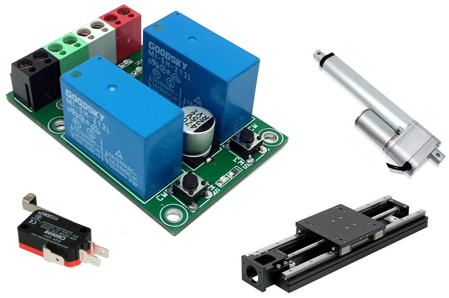
The project described here is a very useful device for use with linear actuators. This controller prevents the actuator from reaching the physical movement limits of the actuator, thus it prevents burnout of motor and physical/mechanical damage to the actuator itself to the mechanical machine associated with it. It also allows for a smoother stopping motion once the end of travel is reached. The project is capable to drive DC brushed motor up to 3A, it supports 12V DC or 24V DC motors with few changes. Two limit switches are used on both sides of the actuator. The limit switches are available with 2 contacts normally open and normally closed. It is advisable to use normally closed contacts. The project consists of 2 DPDT relays, two 1N5402 diodes, Power LED, Motor direction LEDs, 2 x tactile switches, DC supply capacitor, screw terminals, etc.
Operation
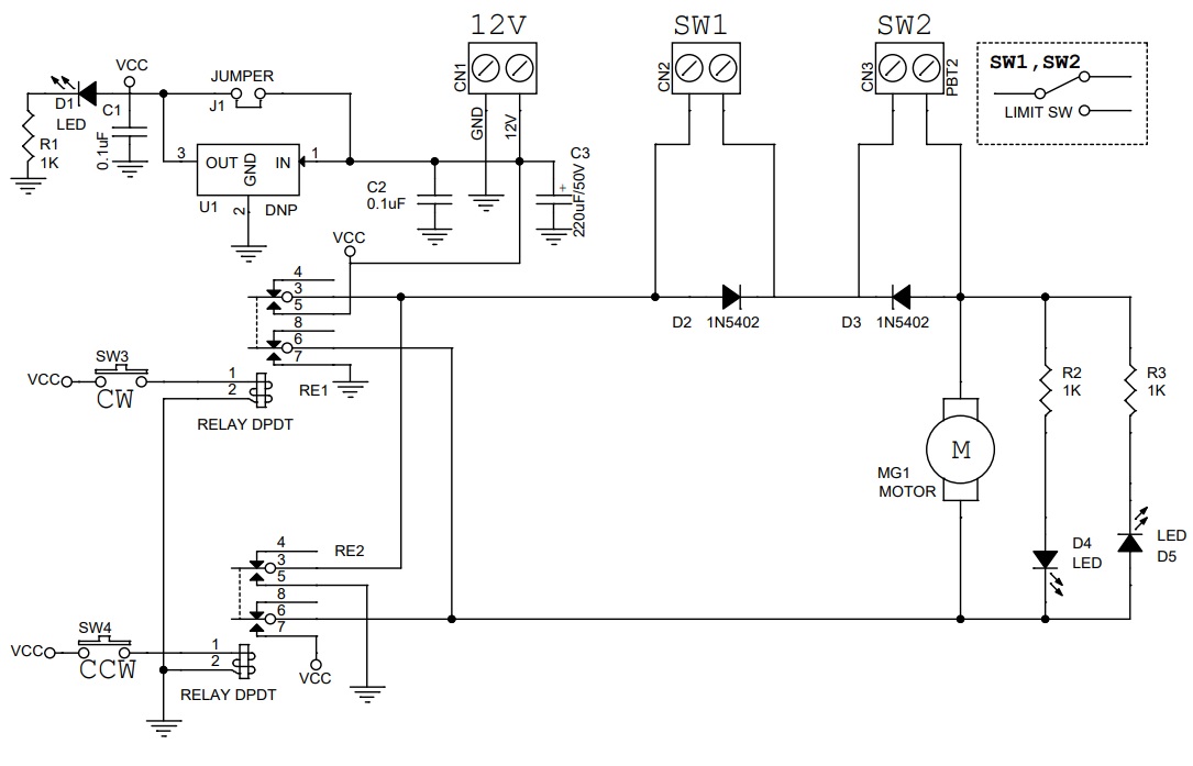
Make all the connections as per the diagram, and install the limit switches at the end of the actuator. It is important to provide little offset space for motor movement. Power the board. Press any of the tactile switches SW1 or Sw2, actuator starts moving in one direction, once it hit the end limit switch, the switch is open, and the diode which is connected across the switch stops the current flow in that direction, and the motor stops. Now press the other switch, in this case, the current flow is reversed and the associated diode allows the motor to run in reverse directions and continue till it hit the other side of the limit switch. It is important to check the motor direction as per diode polarity, and swap the motor connections if the system doesn’t work properly or misbehaves.
12V DC Motor
- Do Not Use Regulator U1, Jumper J1 closed, rest components as per schematic.
24V DC Motor
- Open the Jumper J1
- Resistor Value R1, R2, and R3 = 2.2K Ohms
- Install U1 Regulator LM7812
- In the case of a 24V Relay, don’t install the regulator, and use jumper J1.
Features
- Motor Supply 12V DC (for 24V Motor Read Note)
- Maximum Load Current 3A
- 2 x Tactile switch to drive Motor in CW/CCW
- 2 x LEDs for Motor Direction
- On-Board Power LED
- Screw Terminals for Motor Connections, Limit Switch, Power Supply
- 4 x 3mm Mounting Holes
- PCB Dimensions 63.98 x 43.18 mm
Applications
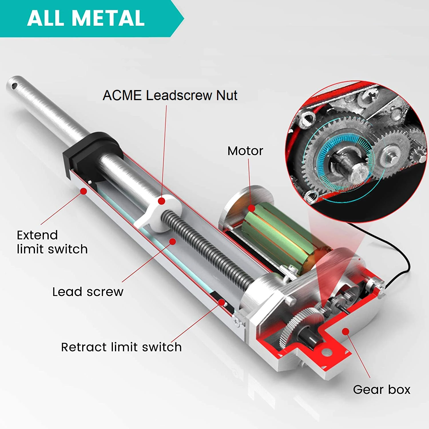
- Linear Actuators
- Rotary Actuators
- Machines
- Automation
- Furniture (Hospital Beds)
Schematic
Parts List
| NO | QNTY. | REF. | DESC. | MANUFACTURER | SUPPLIER | PART NO |
|---|---|---|---|---|---|---|
| 1 | 3 | CN1,CN2,CN3 | 2 PIN SCREW TERMINAL PITCH 5.08MM | PHOENIX | DIGIKEY | 277-1247-ND |
| 2 | 2 | C1,C2 | 0.1uF/50V SMD SIZE 0805 | YAGEO/MURATA | DIGIKEY | |
| 3 | 1 | C3 | 220uF/50V OR 470uF/35V | WURTH | DIGIKEY | 732-8463-1-ND |
| 4 | 3 | D1,D4,D5 | LED SMD SIZE 0805 | LITE ON INC | DIGIKEY | 160-1427-1-ND |
| 5 | 2 | D2,D3 | 1N5402 | SMC DIODE SOL. | DIGIKEY | 1655-1N5402CT-ND |
| 6 | 1 | J1 | 2 PIN MALE HEADER PITCH 2.54MM | WURTH | DIGIKEY | 732-5315-ND |
| 7 | 1 | MG1 | 2 PIN SCREW TERMINAL PITCH 5.08MM | PHOENIX | DIGIKEY | 277-1247-ND |
| 8 | 2 | RE1,RE2 | RELAY DPDT | OMRON | DIGIKEY | G2RL-24 DC12 |
| 9 | 3 | R1,R2,R3 | 1K 5% SMD SIZE 0805 | YAGEO/MURATA | DIGIKEY | |
| 10 | 2 | SW3,SW4 | TACTILE SWITCH | NKK SWITCH | DIGIKEY | HP0215AFKP2-ND |
| 11 | 1 | J1 | JUMPER SHUNT | SULLIN INC | DIGIKEY | S9001-ND |
| 12 | 1 | U1 | LM7812 | TI | DIGIKEY | DNP |
| RE1 & RE2 : | 12VDC Coil Through Hole | General Purpose Relay DPDT (2 Form C) | ||||
| RE1 & RE2 : | OMRON Or Goodsky | MI-SH-212L |
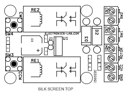
Connections
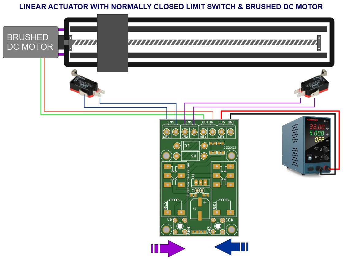
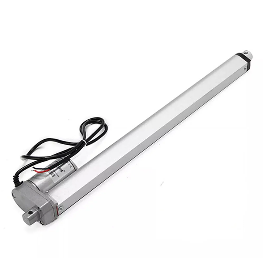
Linear Actuator Diagram
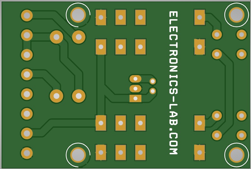
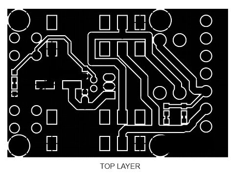
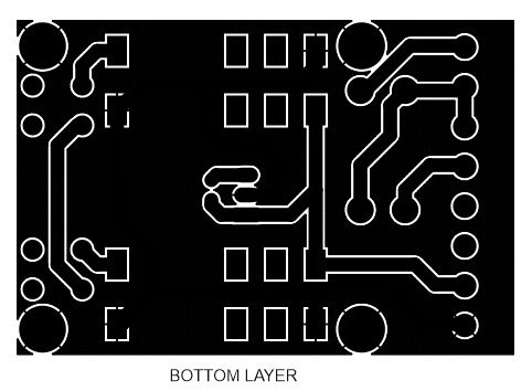
Gerber View
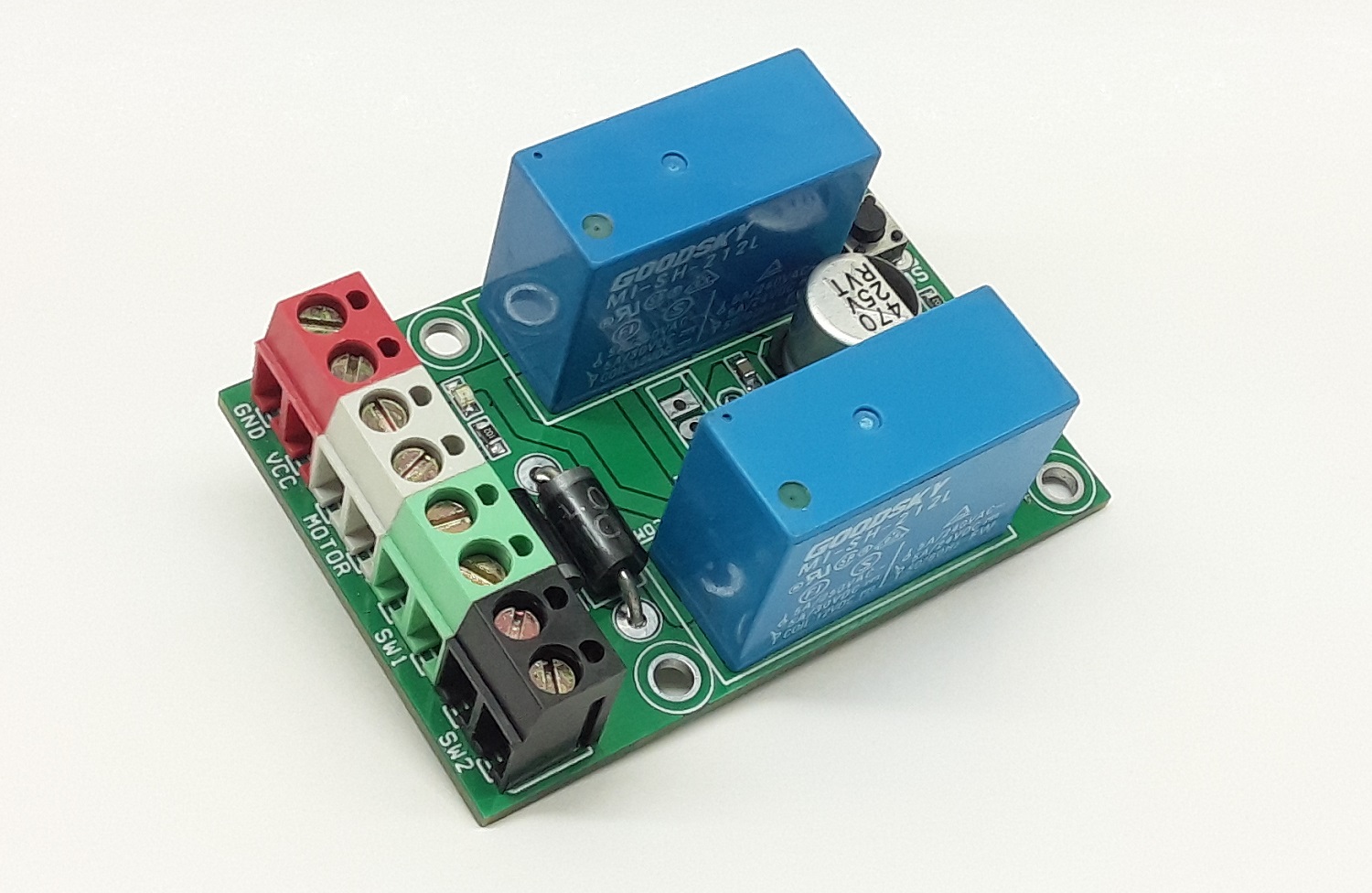
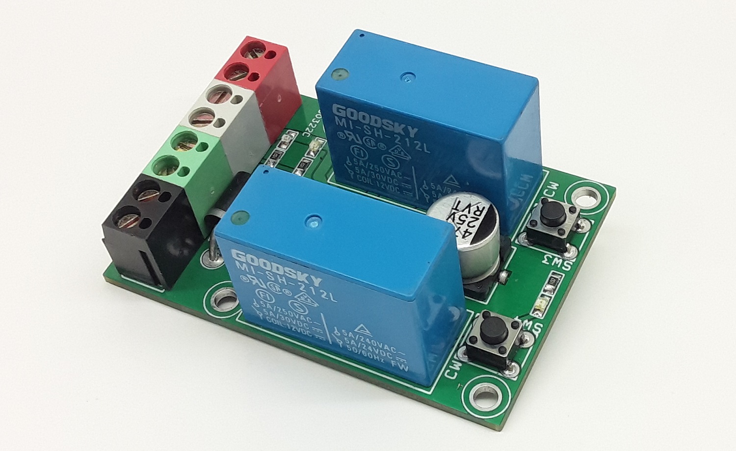
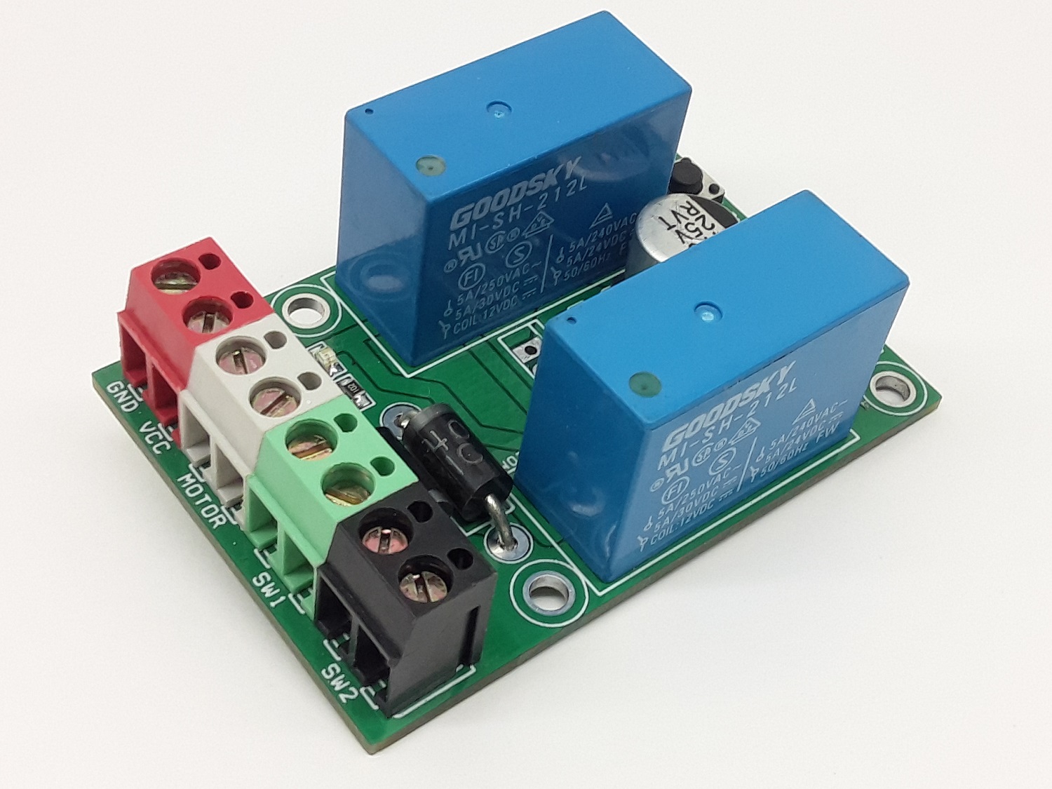
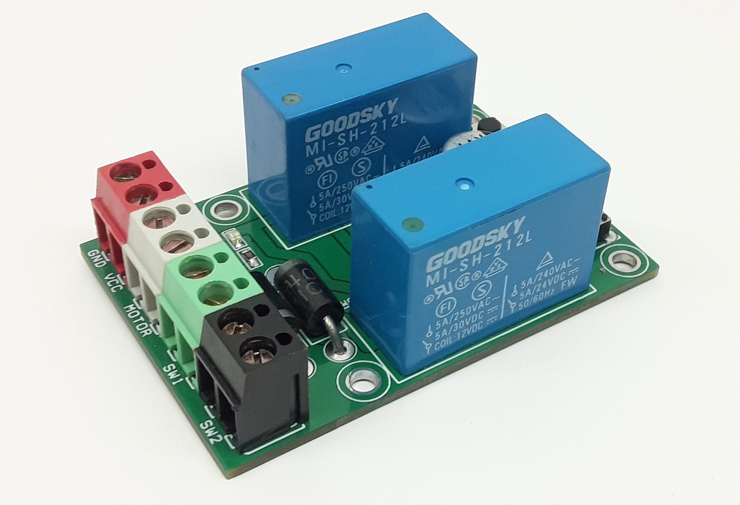
Photos
Video
MI-SH-212L Datasheet
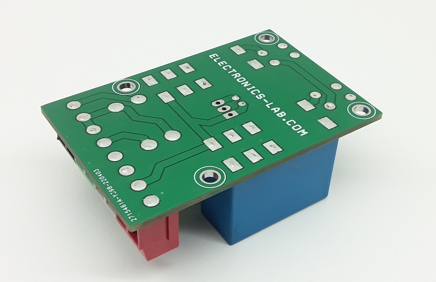
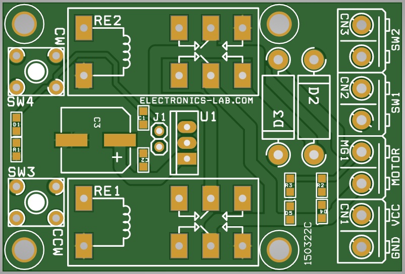
PCB
.png)