

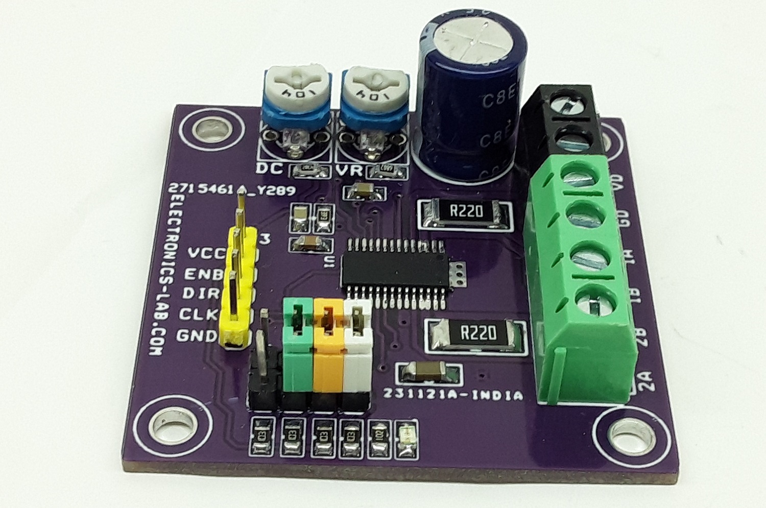
High-performance, High-reliability Bipolar Stepper Motor Driver
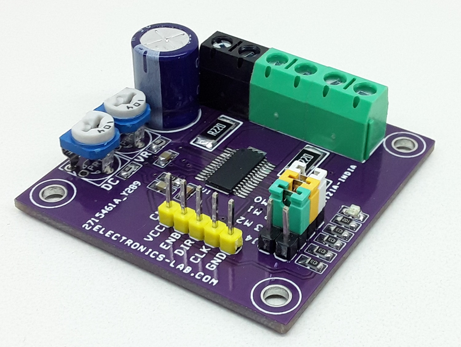
The project presented here is a bipolar stepper motor driver. It is based on BD63731EFV chip which is a low-consumption driver that is driven by a PWM signal. The power supply voltage of the project is 8 to 28V DC, and the rated output current is 3A. CLK-IN driving mode is adopted for the input interface, and excitation mode is corresponding to FULL STEP mode (2 types), HALF STEP mode (2 types), QUARTER STEP mode (2 types), 1/8 STEP mode, and 1/16 STEP mode via a built-in DAC. In terms of current decay, the SLOW DECAY/FAST DECAY ratio may be set without any limitation, and all available modes may be controlled in the most appropriate way. In addition, the power supply may be driven by one single system, which simplifies the design.
Features
- Motor Supply 8 to 28V DC
- Rated Output Current 3.0 A
- Low ON Resistance DMOS Output
- CLK-IN Drive Mode
- PWM Constant Current (other oscillation)
- Built-in Spike Noise Cancel Function (external noise filter is unnecessary)
- FULL STEP (2 types), HALF STEP (2 types),
- QUARTER STEP (2 types), 1/8 STEP, 1/16 STEP Functionality
- Freely Timing Excitation Mode Switch
- Current Decay Mode Switch (linearly variable SLOW/FAST DECAY ratio)
- Normal Rotation & Reverse Rotation Switching Function
- Power Save Function (PS Jumper J4)
- Built-in Logic Input Pull-down Resistor
- Power-on Reset Function
- Thermal Shutdown Circuit (TSD)
- Over-current Protection Circuit (OCP)
- Under Voltage Lock Out Circuit (UVLO)
- Over Voltage Lock Out Circuit (OVLO)
- Protects Against Malfunction when Power Supply is Disconnected (Ghost Supply Prevention Function)
- Adjacent Pins Short Protection
- Microminiature, Ultra-thin and High Heat-radiation (exposed metal type) Package
- PCB Dimensions 45.72 x 45.09mm
Applications
- Sewing Machine
- PPC
- Multi-function Printer
- Laser Beam Printer
- Ink-jet Printer
- Monitoring Camera
- WEB Camera
- Photo Printer
- FAX, Scanner
- Mini Printer
- Toy and Robot
Micro-Stepping
Micro-stepping can be set using the following Jumpers, J1=Mode 0, J2=Mode 1, J3=Mode 2 (Jumper Open = High, Jumper Closed = Low)
- Mode 0=Low, Mode 1=Low, Mode 2=Low >> Full Step A
- Mode 0=High, Mode 1=Low, Mode 2=Low >> Half Step A
- Mode 0=Low, Mode 1=High, Mode 2=Low >> Half Step B
- Mode 0=High, Mode 1=High, Mode 2=Low >> Quarter Step A
- Mode 0=Low, Mode 1=Low, Mode 2=High >> Full Step B
- Mode 0=High, Mode 1=Low, Mode 2=High >> Quarter Step B
- Mode 0=Low, Mode 1=Low, Mode 2=Low >> 1/8 Step
- Mode 0=High, Mode 1=High, Mode 2=High >> 1/16 Step
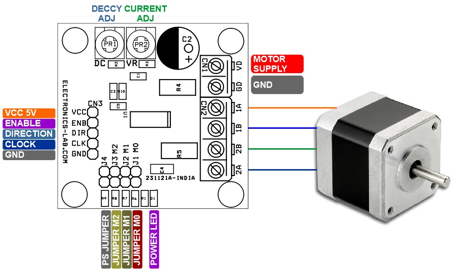
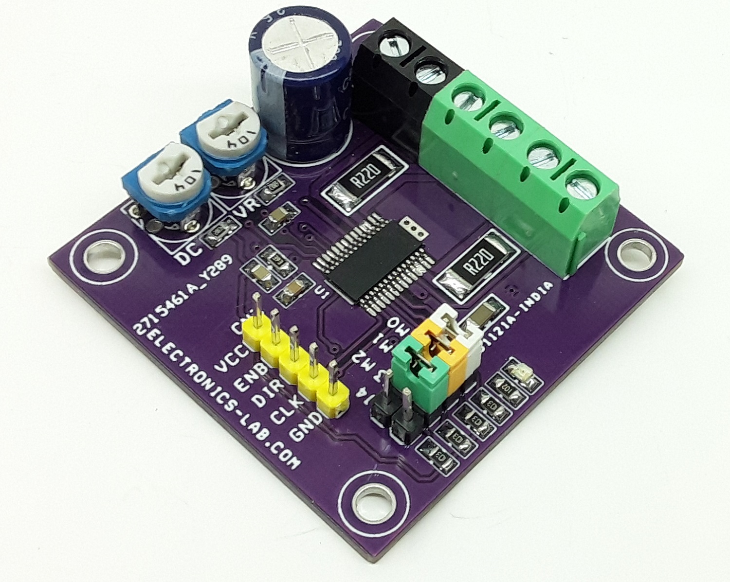
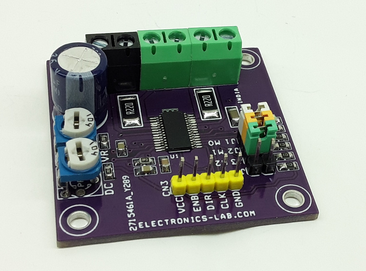
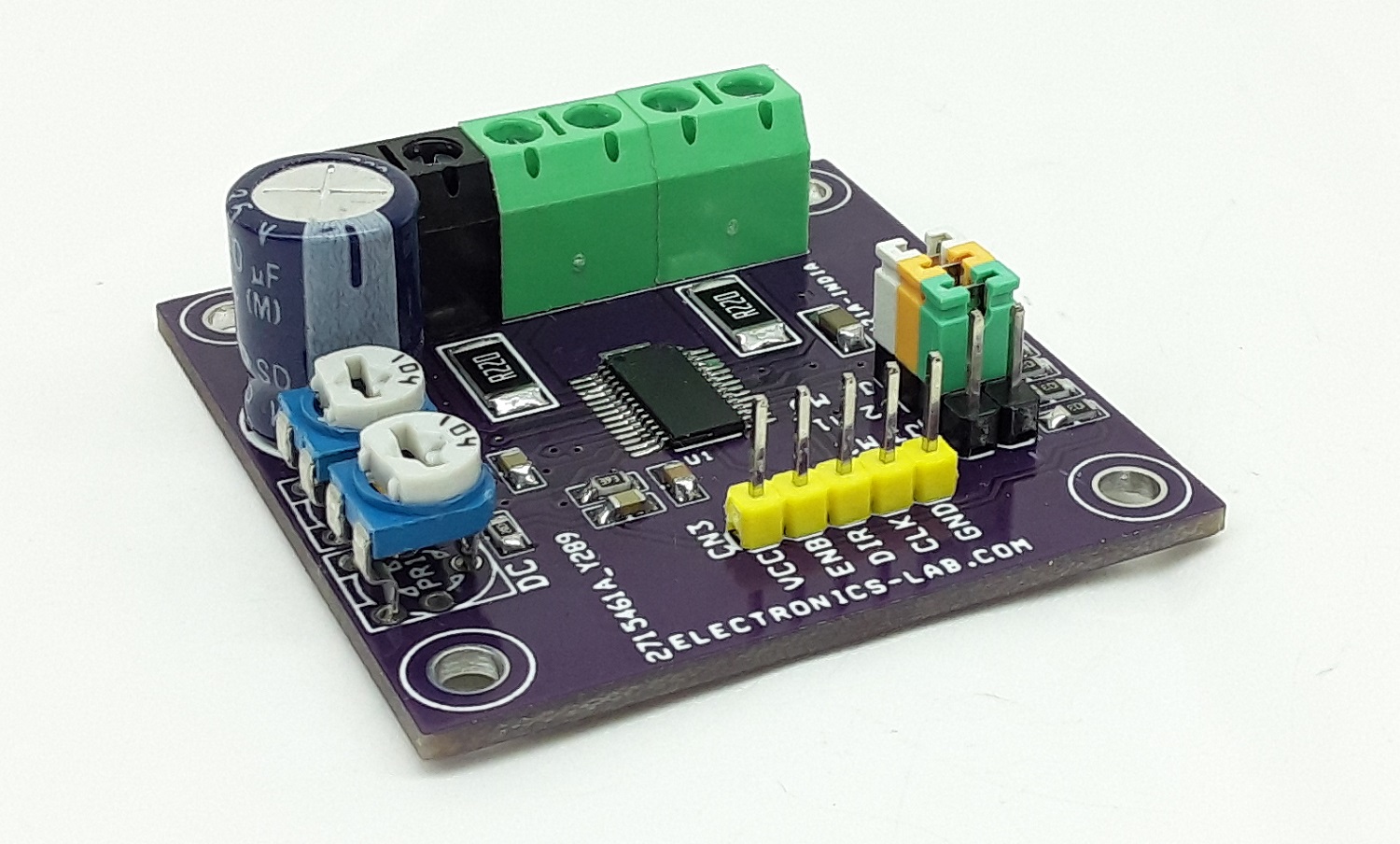
Connector CN3
- Pin1 = VCC 5V Logic Supply In
- Pin2= Enable (Pull High= Enable, Low = Disabled)
- Pin3= Motor Direction (High=CCW, Low CW)
- Pin4= Motor Clock Input (Pulse Input)
- Pin5= GND
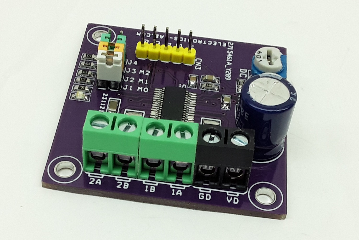
Connector CN2: Bipolar Stepper Motor Connections
Connector CN1: Motor Supply Input 8 to 28V DC
LED D1 = Power LED
PR2 Trimmer Potentiometer: Motor Current Adjustment = 0 to 3V
Jumper J4 PS/Power Save Jumper J4
The PS pin can make circuit in standby state and make motor output OPEN. In the standby state, the translator circuit is RESET (initialized) and the electrical angle is initialized. When PS=L to H, be careful because there is a delay of 40 μs (Max) before it is returned from standby state to normal state and the motor output becomes ACTIVE
PR1 Trimmer Potentiometer: Decay Adjust
- 0 to 0.3V Slow Decay
- 4V to 1V Mix Decay
- 5V to 2V Fast Decay
- 1V to 3.5V Auto Decay
SLOW DECAY
The output current ripple is small and this is favorable for keeping motor torque high because the voltage between the motor coils is small and the regenerative current decreases slowly. However, an increase in the output current due to deterioration of the current control in the lower current operation in HALF STEP, QUARTER STEP, 1/8 STEP, 1/16 STEP, due to the influence of the motor reverse electromotive voltage during high pulse rate driving in the mode, the current waveform is not able to follow the change in the current limit and the distortion and motor vibration increases. Thus, this decay mode is suited to FULL STEP mode or low-pulse-rate driven HALF STEP, QUARTER STEP, 1/8 STEP or 1/16 STEP modes.
FAST DECAY
Fast decay decreases the regeneration current much more quickly than slow decay, reducing distortion of the output current waveform. However, fast decay yields a much larger output current ripple, which decreases the overall average current running through the motor. This causes two problems: first, the motor torque decreases (increasing the current limit value can help eliminate this problem, but the rated output current must be taken into consideration); and second, the power loss within the motor increases and thereby radiates more heat. If neither of these problems is of concern, then fast decay can be used for high-pulse rate HALF STEP, QUARTER STEP, 1/8 STEP or 1/16 STEP drive. Additionally, this IC allows for MIX DECAY mode/AUTO DECAY mode that can help to improve upon problems that arise from using fast or slow decay.
MIX DECAY
During current decay Switching between SLOW DECAY and FAST DECAY can improve current control without increasing the current ripple. In addition, the time ratio of SLOW DECAY and FAST DECAY can be changed by the voltage input to the MTH pin, and it is possible to achieve an optimal control state for any motor. During MIX DECAY mode about chopping cycle, the first (t1 to t2) of which operates the IC in SLOW DECAY mode, and the remainder (t2 to t3) of which operates in FAST DECAY mode. However, if the output current does not reach the set current limit during the first (t1 to t2) decay period, the IC operates in fast decay mode only.
AUTO DECAY
Current control capability can still be improved without making the current ripple big by using SLOW DECAY and switches only to FAST DECAY when required. Decay mode becomes FAST DECAY only when output current reaches the set value while at minimum ON time.
Protection Circuits
1.Thermal Shutdown (TSD)
This IC has a built-in thermal shutdown circuit for thermal protection. When the IC’s chip temperature rises 175 °C (Typ) or more, the motor output becomes OPEN. Also, when the temperature returns to 150 °C (Typ) or less, it automatically returns to normal operation. However, even when TSD is in operation, if heat is continued to be added externally, heat overdrive can lead to destruction.
2. Over Current Protection (OCP)
This IC has a built-in over current protection circuit as a provision against destruction when the motor outputs are shorted each other or VCC-motor output or motor output-GND is shorted. This circuit latches the motor output to OPEN condition when the regulated current flows for 4 μs (Typ). It returns with power reactivation or a reset by the PS pin. The over current protection circuit’s only aim is to prevent the destruction of the IC from irregular situations such as motor output shorts, and is not meant to be used as protection or security for the set. Therefore, sets should not be designed to take into account this circuit’s functions. After OCP operating, if irregular situations continue and the return by power reactivation or a reset by the PS pin, then OCP operates repeatedly and the IC may generate heat or otherwise deteriorate. When the L value of the wiring is great due to the wiring being long, the motor outputs are shorted each other or VCC-motor output or motor output-GND is shorted., if the output pin voltage jumps up and the absolute maximum values can be exceeded after the over current has flowed, there is a possibility of destruction. Also, when current which is the output current rating or more and the OCP detection current or less flows, the IC can heat up to Tjmax=150 °C exceeds and can deteriorate, so current which or more the output rating should not be applied.
3. Under Voltage Lock Out (UVLO)
This IC has a built-in under voltage lock out function to prevent false operation such as IC output during power supply under voltage is low. When the applied voltage to the VCCX pin goes 5 V (Typ) or less, the motor output is set to OPEN. This switching voltage has a 1 V (Typ) hysteresis to prevent false operation by noise etc. Be aware that this circuit does not operate during power save mode. Also, the electrical angle is reset when he UVLO circuit operates.
4. Over Voltage Lock Out (OVLO)
This IC has a built-in over voltage lock out function to protect the IC output and the motor during power supply over voltage. When the applied voltage to the VCCX pin goes 32 V (Typ) or more, the motor output is set to OPEN. This switching voltage has a 1 V (Typ) hysteresis and a 4 μs (Typ) mask time to prevent false operation by noise etc. Although this over voltage locked out circuit is built-in, there is a possibility of destruction if the absolute maximum value for power supply voltage is exceeded. Therefore, the absolute maximum value should not be exceeded. Be aware that this circuit does not operate during power save mode.
5. Protects against malfunction when power supply is disconnected (Ghost Supply Prevention Function)
If a control signal is input when there is no power supplied to this IC, there is a function which prevents a malfunction where voltage is supplied to power supply of this IC or other IC in the set via the electrostatic destruction prevention diode from these input pins to the VCCX. Therefore, there is no malfunction of the circuit even when voltage is supplied to these input pins while there is no power supply. (Note 1) control signal=CLK, CW_CCW, MODE0, MODE1, MODE2, ENABLE, PS, MTH, VREF
6. Operation Under Strong Electromagnetic Field
The IC is not designed for using in the presence of strong electromagnetic field. Be sure to confirm that no malfunction is found when using the IC in a strong electromagnetic field.
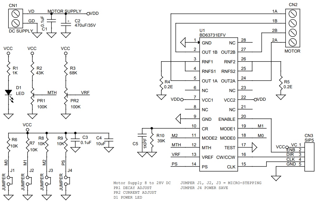
Schematic
Parts List
| NO | QNTY. | REF. | DESC | MANUFACTURER | SUPPLIER | PART NO |
|---|---|---|---|---|---|---|
| 1 | 1 | CN1 | 2 PIN SCREW TERMINAL PITCH 5.08MM | PHOENIX | DIGIKEY | 277-1247-ND |
| 2 | 2 | CN2 | 2 PIN SCREW TERMINAL PITCH 5.08MM | PHOENIX | DIGIKEY | 277-1247-ND |
| 3 | 1 | CN3 | 5 PIN MALE HEADER PITCH 2.54MM | WURTH | DIGIKEY | 732-5318-ND |
| 4 | 2 | C1,C3 | 0.1uF/50V SMD SIZE 0895 | MURATA/YAGEO | DIGIKEY | |
| 5 | 1 | C2 | 470uF/35V | NICHICON | DIGIKEY | UHE1V471MHD6CT-ND |
| 6 | 1 | C4 | 10uF/6.3V SMD SIZE 1206 | MURATA/YAGEO | DIGIKEY | |
| 7 | 1 | C5 | 1KPF/50V SMD SIZE 0805 | MURATA/YAGEO | DIGIKEY | |
| 8 | 1 | D1 | LED SMD SIZE 0805 | LITE ON INC | DIGIKEY | 160-1427-1-ND |
| 9 | 4 | J1,J2,J3,J4 | JUMPER | WURTH | DIGIKEY | 732-5315-ND |
| 10 | 2 | PR1,PR2 | 100K TRIMMER POTENTIOMETER | BOURNS INC | DIGIKEY | 3362F-1-104LF-ND |
| 11 | 1 | R1 | 1K 5% SMD SIZE 0805 | MURATA/YAGEO | DIGIKEY | |
| 12 | 1 | R2 | 43K 5% SMD SIZE 0805 | MURATA/YAGEO | DIGIKEY | |
| 13 | 1 | R3 | 68K 5% SMD SIZE 0805 | MURATA/YAGEO | DIGIKEY | |
| 14 | 2 | R4,R5 | 0.2E/2W SMD SIZE 2512 | BOURNS INC | DIGIKEY | CRM2512-FX-R200ELFTR-ND |
| 15 | 4 | R6,R7,R8,R9 | 10K 5% SMD SIZE 0805 | MURATA/YAGEO | DIGIKEY | |
| 16 | 1 | R10 | 39K 5% SMD SIZE 0805 | MURATA/YAGEO | DIGIKEY | |
| 17 | 1 | U1 | BD63731EFV | ROHM | ELEMENT14 | 3778768 |
| 18 | 4 | SHUNT | JUMPER SHUNT PITCH 2.54MM | SULLINS CONNCT | DIGIKEY | S9001-ND |
Connections
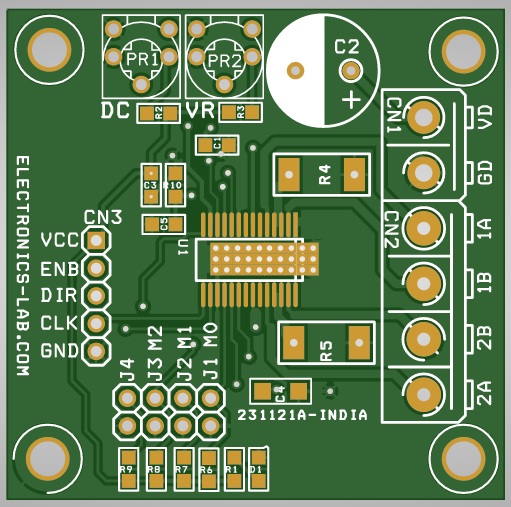
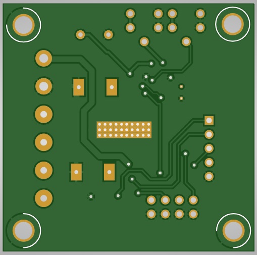
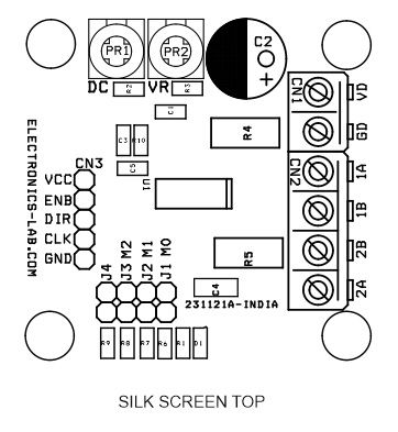
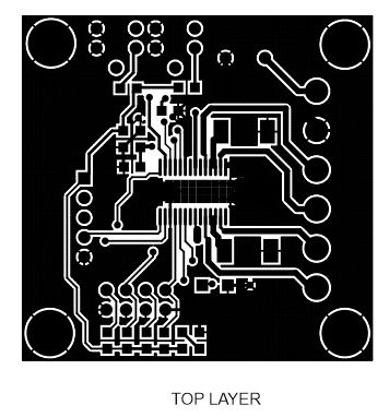
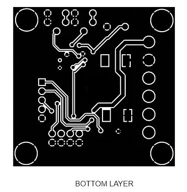
Gerber View
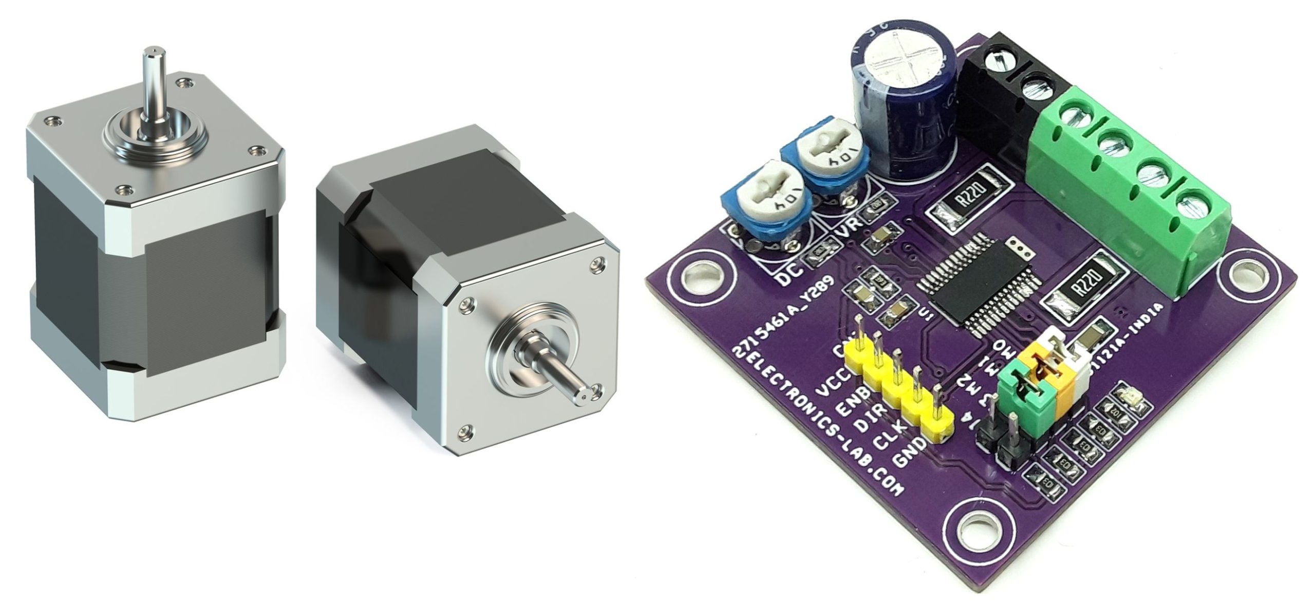
Photos

Video
BD63731EFV Datasheet
PCB
.png)