3-Phase Brushless DC Sinusoidal Sensorless Fan Motor Driver
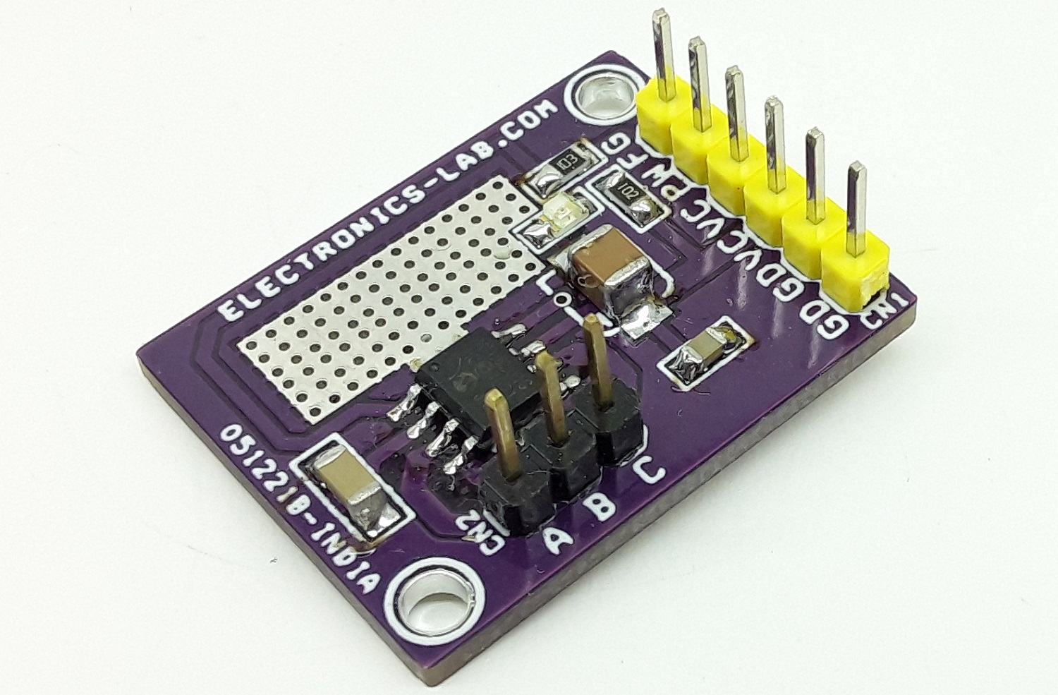
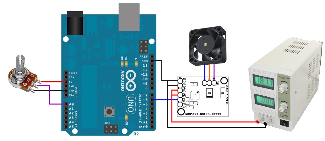
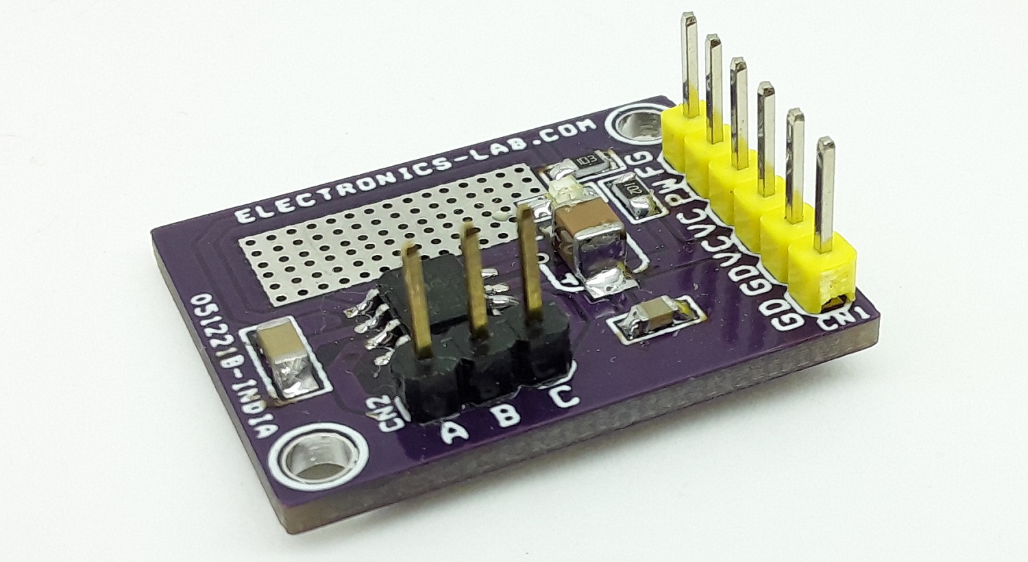
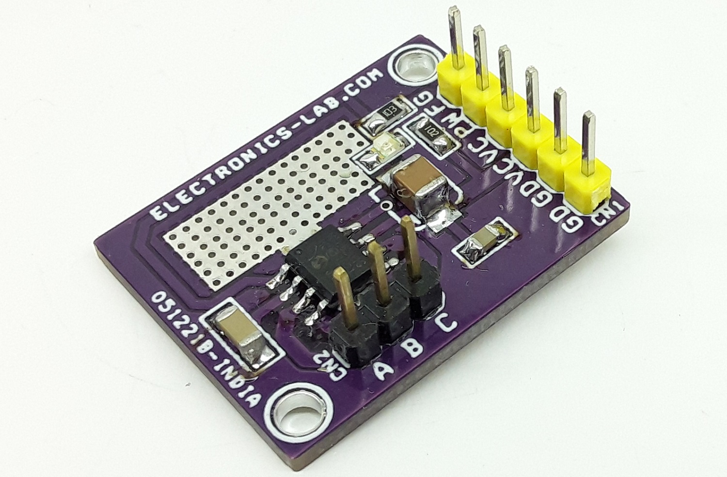
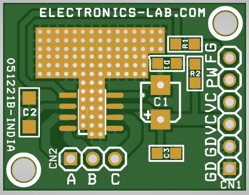
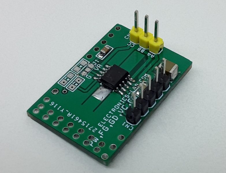
Driving a low current 3 phase brushless Sensorless DC motor is very easy with this project. This Full-wave BLDC driver project is capable to drive low current brushless fan motor without a hall sensor. 180° sinusoidal drive, high torque output, and silent drive are a few key features of the project. Due to their adaptive features and wide power-supply range capabilities (3 to 12V) they are intended to cover a wide range of motor characteristics while requiring no external tuning from the user. Speed control can be achieved through either power supply modulation or pulse-width-modulation (using the PWM digital input pin5 of CN1). Due to the compact packaging and minimum bill-of-material (power transistors incorporated, no Hall sensor, no external tuning), the project is best suited for low-cost fan applications requiring high efficiency and low acoustic noise, such as CPU cooling fans. The frequency generator output is also included, enabling precision speed control in closed-loop applications. Motor over-current limitation, short-circuit protection, and thermal shutdown protection is also included. Connect 3 Phase Motor to CN2, Apply Motor Supply to GND and VCC of CN1, Apply PWM signal to PIN 5 of CN1. D1 Power LED.
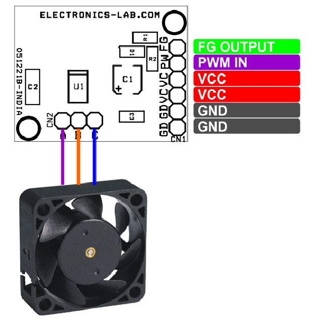
Connections CN1
- Pin 6: FG Frequency Generator Output (Feedback Signal Output)
- Pin5: PWM Signal Input (Frequency 20Hz to 100Khz, Duty Cycle 0 to 100%)
- Pin4: VCC 3V to 12V DC Positive
- Pin3: VCC 3V to 12V DC Positive
- Pin 2: GND
- Pin1: GND
Connector CN2: 3 Phase Brushless Motor
Features
- Supply 3V To 12V DC (Range 2V To 14V DC)
- Maximum Output Current 800mA
- Output Frequency 23Khz
- Position Sensorless BLDC drivers (no Hall sensor required)
- 180° sinusoidal drive, for high efficiency and low acoustic noise
- Speed control through PAM and/or PWM
- Built-in frequency generator
- Built-in lockup protection and automatic recovery circuit (external capacitor not necessary)
- Built-in overcurrent limitation and short circuit protection
- Built-in thermal shutdown protection
- No external tuning required
- PCB Dimensions 27.94 x 21.59mm
Speed Control (CN1 Pin 5)
The rotational speed of the motor can be controlled either through the PWM digital input signal or by acting directly on the power supply (VCC). When the PWM signal is “High” (or left open) the motor rotates at full speed. When the PWM signal is “Low”, the motor is stopped (and the IC outputs are set to high impedance). By changing the PWM duty cycle, the speed can be adjusted. Notice that the PWM frequency has no special meaning for the motor speed and is asynchronous with the activation of the output transistors. Thus, the user has maximum freedom to choose the PWM system frequency within a wide range (from 20 Hz to 100 kHz), while the output transistor activation always occurs at a fixed rate, which is outside of the range of audible frequencies. The MTD6501G output frequency is 23 kHz.
FG -Frequency Generator Function (CN1 Pin 6)
The Frequency Generator output is a “Hall-sensor equivalent” digital output, giving information to an external controller about the speed and phase of the motor. The FG pin is an open drain output, connecting to a logical voltage level through an external pull-up resistor. When a lock (or out-of-sync) situation is detected by the driver, this output is set to high-impedance until the motor is restarted. Leave the pin open when not used. The FG signal can be used to compute the motor speed in rotations per minute (RPM). Typically, for a four pole BLDC fan, the speed in RPMs is 30 FG frequency (Hz)
Lockup Protection and Automatic Restart
If the motor is stopped (blocked) or if it loses synchronization with the driver, a lock-up protection circuit detects this situation and disables the driver (by setting its outputs to high-impedance) in order to prevent the motor coil from burnout. After a “waiting time” (TWAIT), the lock-up protection is released and normal operation resumes for a given time (TRUN). In case the motor is still blocked, a new period of waiting time is started. TWAIT and TRUN timings are fixed internally, so that no external capacitor is needed.
Overcurrent Protection and Short Circuit Detection
The motor peak current is limited by the driver to a fixed value (defined internally), thus limiting the maximum power dissipation in the coils. The detection of a short-circuit situation immediately sets the driver outputs to high-impedance, in order to avoid permanent damage to the IC
Thermal Shutdown
The MTD6501G Chip have a thermal protection function which detects when the die temperature exceeds TSD = +170°C. When this temperature is reached, the circuit enters Thermal Shutdown mode and the outputs OUT1, OUT2 and OUT3 are disabled (high-impedance), avoiding IC destruction and allowing the circuit to cool down. Once the junction temperature (TSD) has dropped below +145°C, the normal operation resumes (thermal detection circuit has +25°C hysteresis function).
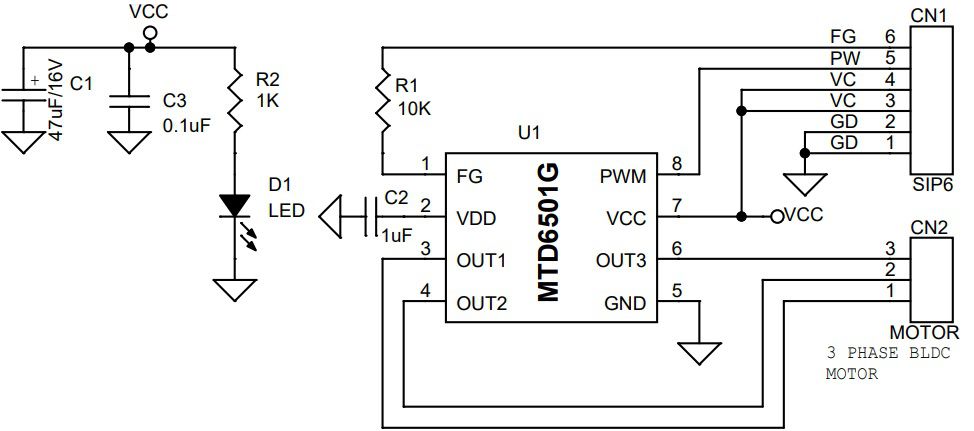
Schematic
Parts List
| NO | QNTY. | REF | DESC. | MANUFACTURER | SUPPLIER | PART NO |
|---|---|---|---|---|---|---|
| 1 | 1 | CN1 | 6 PIN MALE HEADER PITCH 2.54MM | WURTH | DIGIKEY | 732-5319-ND |
| 2 | 1 | CN2 | 3 PIN MALE HEADER PITCH 2.54MM | WURTH | DIGIKEY | 732-5316-ND |
| 3 | 1 | C1 | 47uF/16V SMD SIZE 1210 | MURATA/YAGEO | DIGIKEY | |
| 4 | 1 | C2 | 1uF/16V SMD SIZE 1206 | MURATA/YAGEO | DIGIKEY | |
| 5 | 1 | C3 | 0.1uF/50V SMD SIZE 0805 | MURATA/YAGEO | DIGIKEY | |
| 6 | 1 | D1 | LED SMD SIZE 0805 | LITE ON INC | DIGIKEY | 160-1427-1-ND |
| 7 | 1 | R1 | 10K 5% SMD SIZE 0805 | MURATA/YAGEO | DIGIKEY | |
| 8 | 1 | R2 | 1K 5% SMD SIZE 0805 | MURATA/YAGEO | DIGIKEY | |
| 9 | 1 | U1 | MTD6501G | MICROCHIP | DIGIKEY | MTD6501G-HC1-ND |
Connections
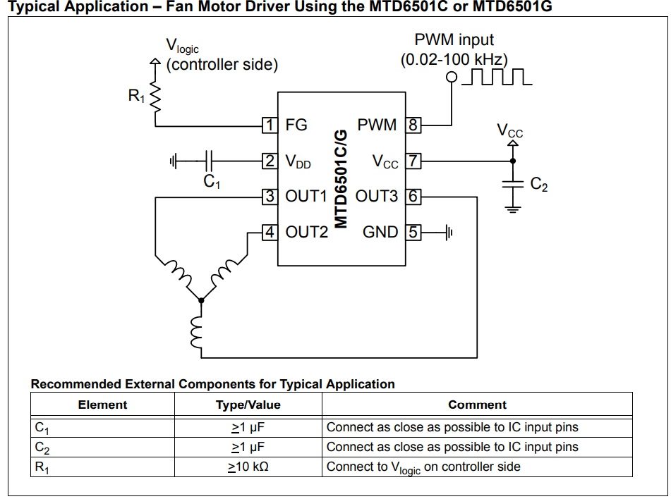
Typical Application
Arduino Diagram




.png)


I have created a electric circuit with this device. It’s awesome to use this module.