PWM Temperature Controlled FAN using TC648 and NTC sensor
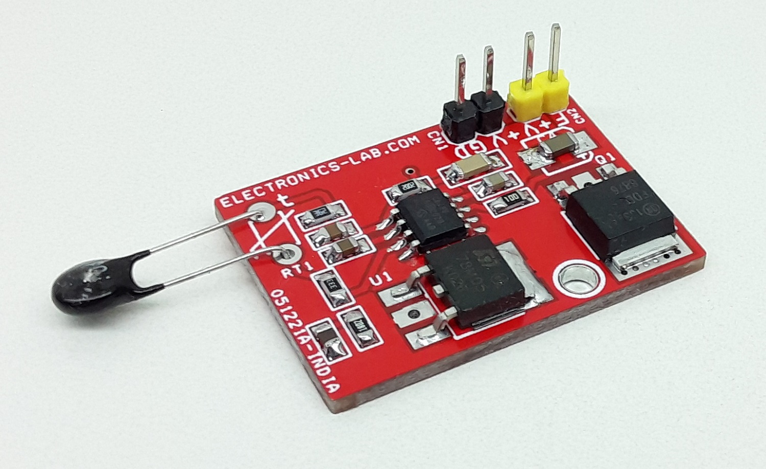
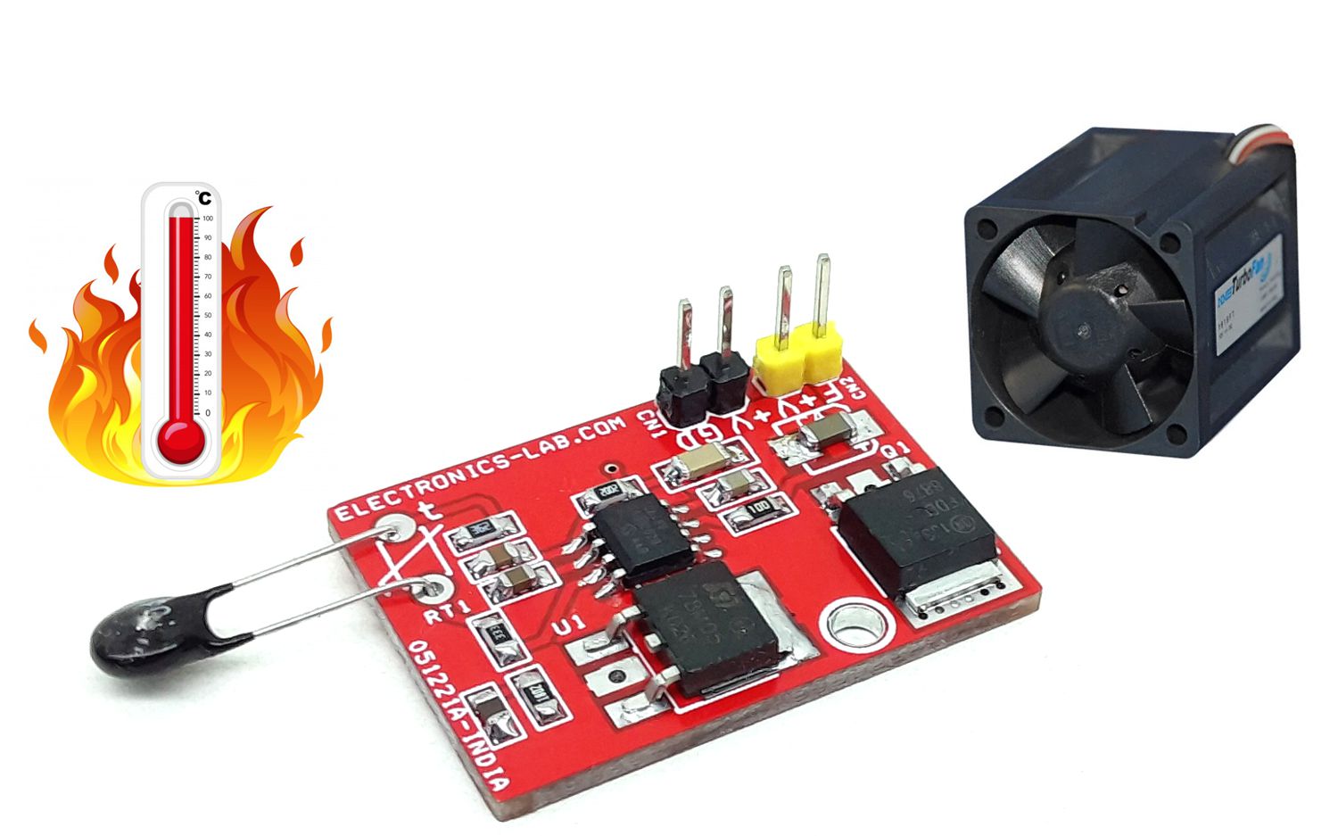
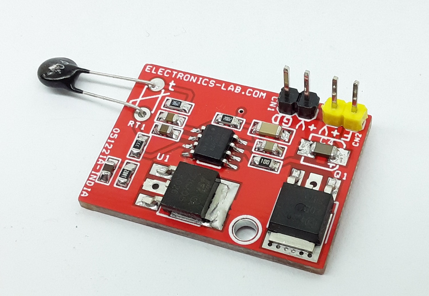
The project described here is a switch mode fan speed controller for use with brushed or brushless DC motors. Temperature proportional speed control is accomplished using pulse width modulation (PWM). 10K Ohms NTC is used to sense the temperature. The project is built using TC648 chip and configured with auto-shutdown mode. In Auto-Shutdown mode, fan operation is automatically suspended when the measured temperature is lower than 25 degrees centigrade. The fan is automatically restarted and proportional speed control is restored when the temperature exceeds 25 degrees centigrade. An integrated Start-Up Timer ensures reliable motor start-up at turn-on, or when coming out of Shutdown mode. MOSFET Q1 is provided to drive the Fan up to 3A of load. A few fans require a PWM signal to work. Use gate of MOSFET to take out the direct PWM signal.
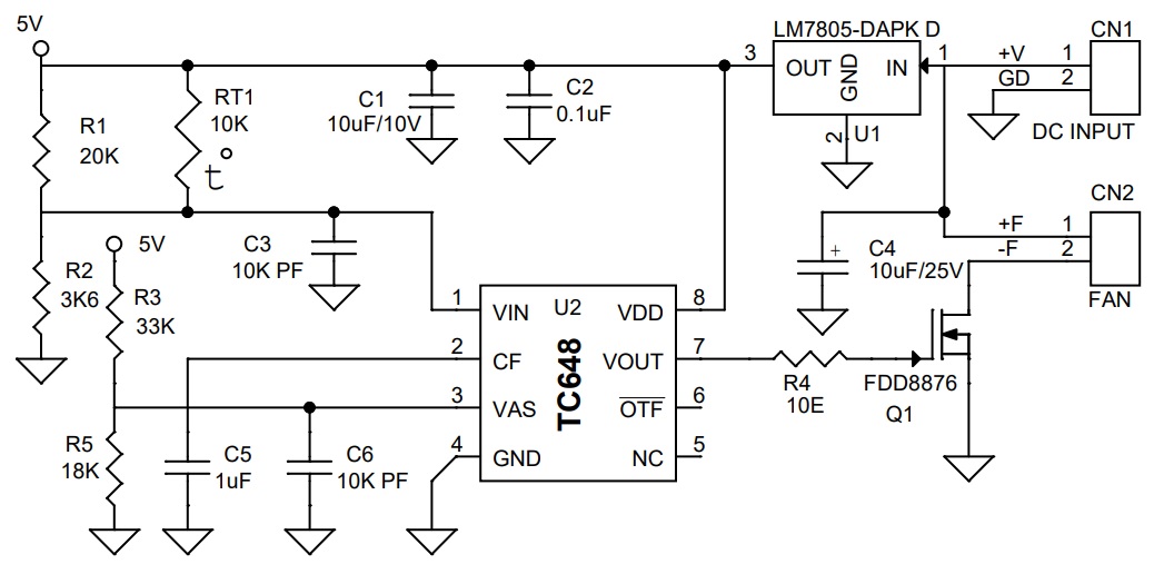
Auto-Shutdown Setting (Resistor Divider R3 and R5)
An external resistors R3 and R5 divider connected to the VAS input sets the auto-shutdown threshold. Auto-shutdown occurs when VIN ≤ VAS. During the shutdown, the supply current falls to 25 µA (typical). The fan is automatically restarted when VIN ≥ (VAS +VHAS).
PWM (Duty Cycle 42% to 100%, 42% is setpoint for minimum speed beyond this shutdown event occurs)
The PWM circuit consists of a ramp generator and threshold detector. The frequency of the PWM is determined by the value of the capacitor connected to the CF pin. A frequency of 30 Hz is selected using CF capacitor C5, PWM is also the time base for the Start-up Timer. The PWM voltage control range is 1.25V to 2.65V (typical) for 0% to 100% output duty cycle.
Start-Up Timer
To ensure reliable fan start-up, the Start-up Timer turns the VOUT output on for 32 cycles of the PWM whenever the fan is started from the off state. This occurs at power-up and when coming out of shutdown or auto-shutdown mode. Start-up time is approximately one second with PWM frequency 30Hz)
Auto shut-Down Mode Calculation
- Calculation R1 and R2 based on using an NTC having a resistance of 10 kΩ at TMIN (25°C) and 4.65 kΩ at TMAX (45°C) R1 = 20 kΩ R2 = 3K6 kΩ
- Set auto-shutdown level. VAS = 1.8V Limit the divider current to 100 µA R3 = 33 kΩ R5 = 18 kΩ
Features
- Operating Supply 12V to 18V
- Fan 12V – 18V DC
- Load up to 3A (12V to 18V)
- PWM Duty Cycle 42% to 100%
- Fan Shut-down when Temperature Falls approx. 25 Degree Centigrade
- Fan Low Speed (42% Duty Cycle) When Temperature 25 Degree Centigrade
- Fan Full Speed (100% Duty Cycle) When Temperature goes Above approx. 45 Degree Centigrade
- PWM Frequency 30 Hz
- Temperature Proportional Fan Speed for Acoustic Control and Longer Fan Life
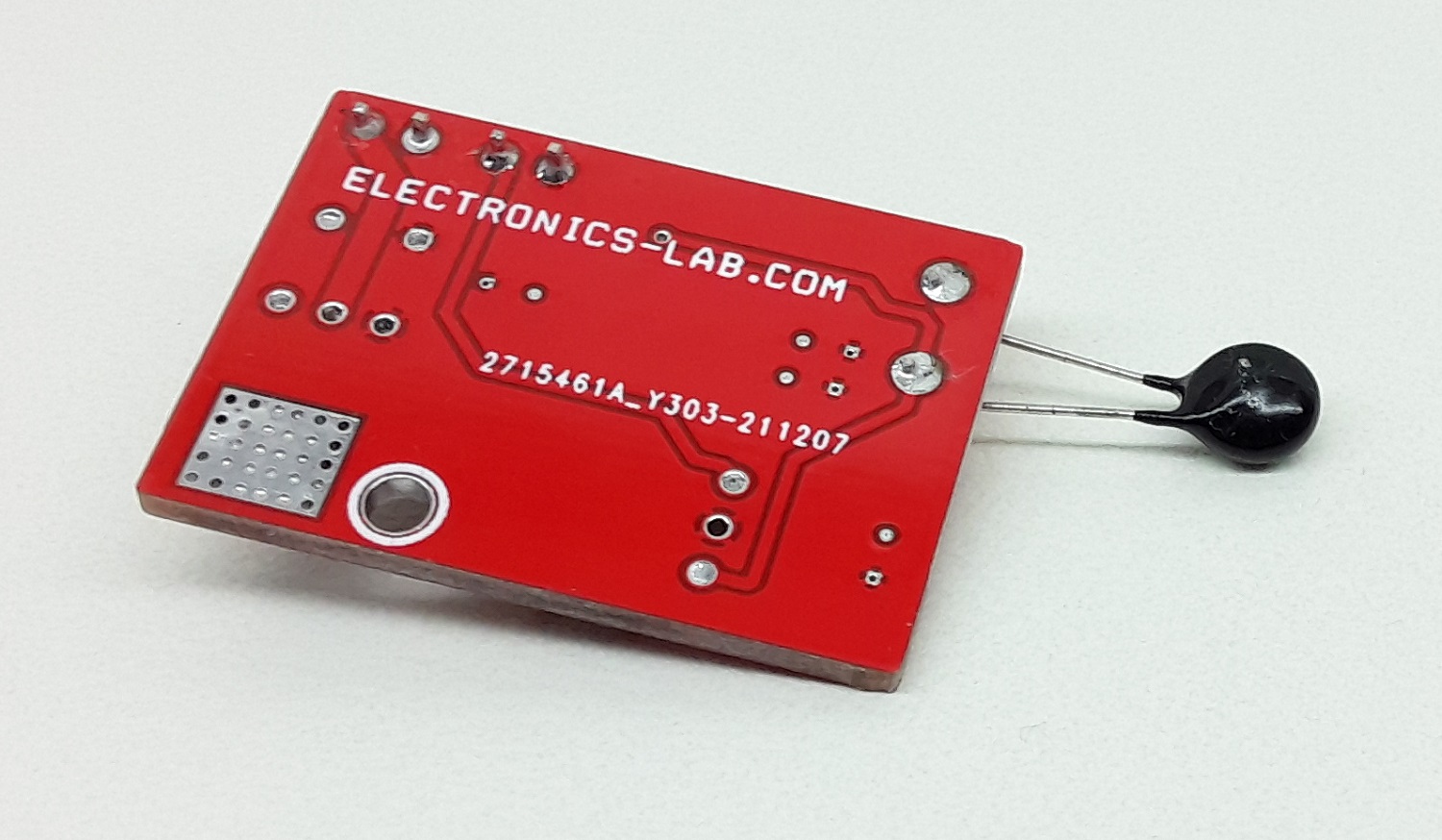
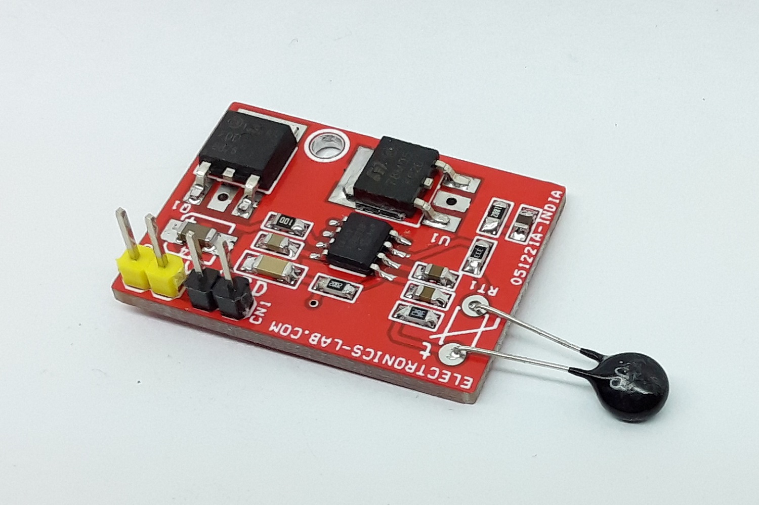
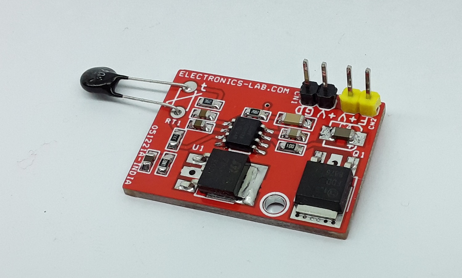
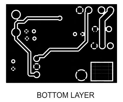
- PCB dimensions: 31.91 x 22.86 mm
Schematic
Parts List
| NO | QNTY. | REF. | DESC. | MANUFACTURER | SUPPLIER | PART NO |
|---|---|---|---|---|---|---|
| 1 | 1 | CN1 | 2 PIN MALE HEADER PITCH 2.54MM | WURTH | DIGIKEY | 732-5315-ND |
| 2 | 1 | CN2 | 2 PIN MALE HEADER PITCH 2.54MM | WURTH | DIGIKEY | 732-5315-ND |
| 3 | 1 | C1 | 10uF/10V SMD SIZE 1206 | MURATA/YAGEO | DIGIKEY | |
| 4 | 1 | C2 | 0.1uF/50V SMD SIZE 0805 | MURATA/YAGEO | DIGIKEY | |
| 5 | 2 | C3,C6 | 10K PF SMD SIZE 0805 | MURATA/YAGEO | DIGIKEY | |
| 6 | 1 | C4 | 10uF/25V SMD SIZE 1210 OR 1206 | MURATA/YAGEO | DIGIKEY | |
| 7 | 1 | Q1 | FDD8876 | ON SEMI | DIGIKEY | FDD8876CT-ND |
| 8 | 1 | RT1 | 10K 5% SMD SIZE 0805 | MURATA/YAGEO | DIGIKEY | |
| 9 | 1 | R1 | 20K 1% SMD SIZE 0805 | MURATA/YAGEO | DIGIKEY | |
| 10 | 1 | R2 | 3K6 1% SMD SIZE 0805 | MURATA/YAGEO | DIGIKEY | |
| 11 | 1 | R3 | 33K 1% SMD SIZE 0805 | MURATA/YAGEO | DIGIKEY | |
| 12 | 1 | R4 | 10E 5% SMD SIZE 0805 | MURATA/YAGEO | DIGIKEY | |
| 13 | 1 | R5 | 18K 1% SMD SIZE 0805 | MURATA/YAGEO | DIGIKEY | |
| 14 | 1 | U1 | LM7805-DAPK D | ON SEMI | DIGIKEY | MC78M05CDTGOS-ND |
| 15 | 1 | U2 | TC648 SOIC8 | MICROCHIP | DIGIKEY | TC648VOA713CT-ND |
| 16 | 1 | C5 | 1uF/10V SMD SIZE 0805 | MURATA/YAGEO | DIGIKEY |
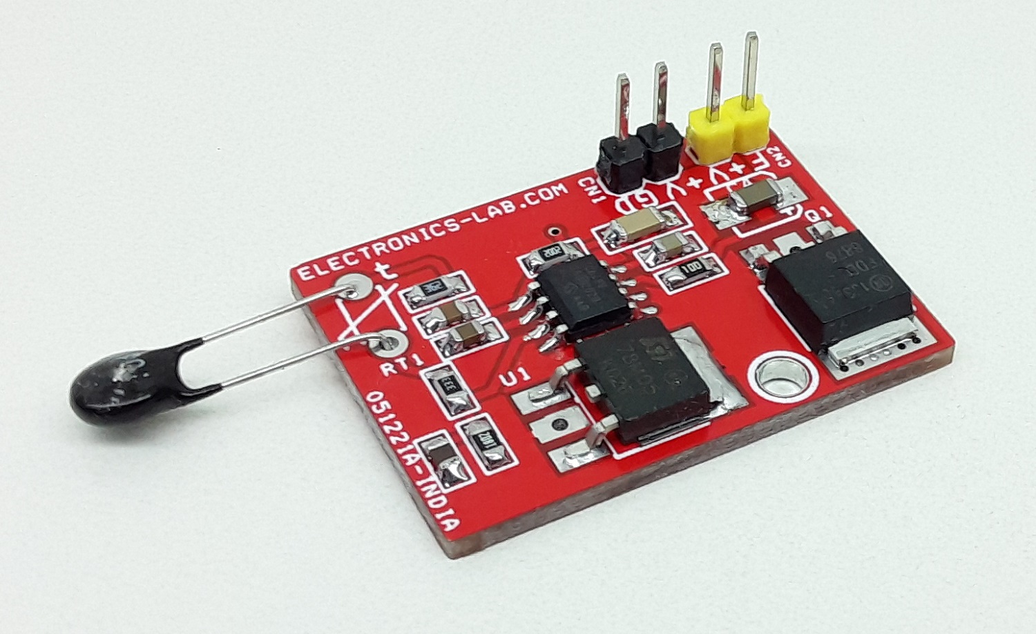
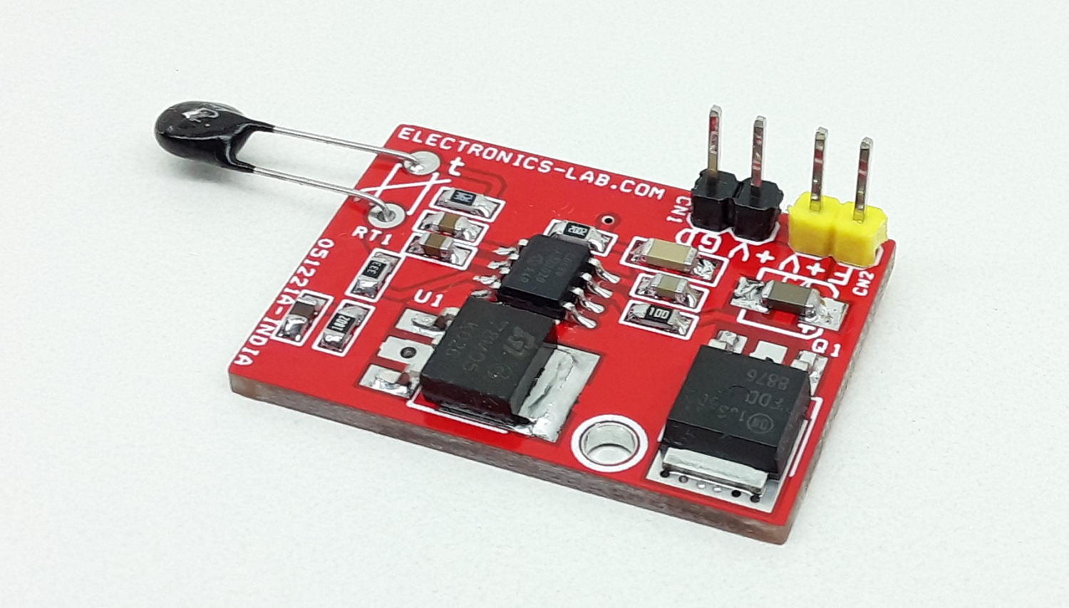
Connections



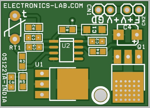
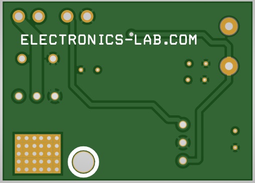
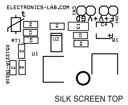
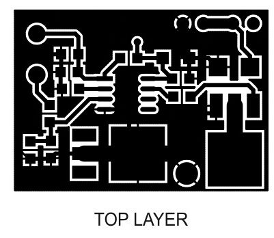

.png)


