
DC Motor Controller using Relay and MOSFET – Arduino Interface
- Rajkumar Sharma
- 294 Views
- moderate
- Tested
- SKU: EL118230
- Quote Now
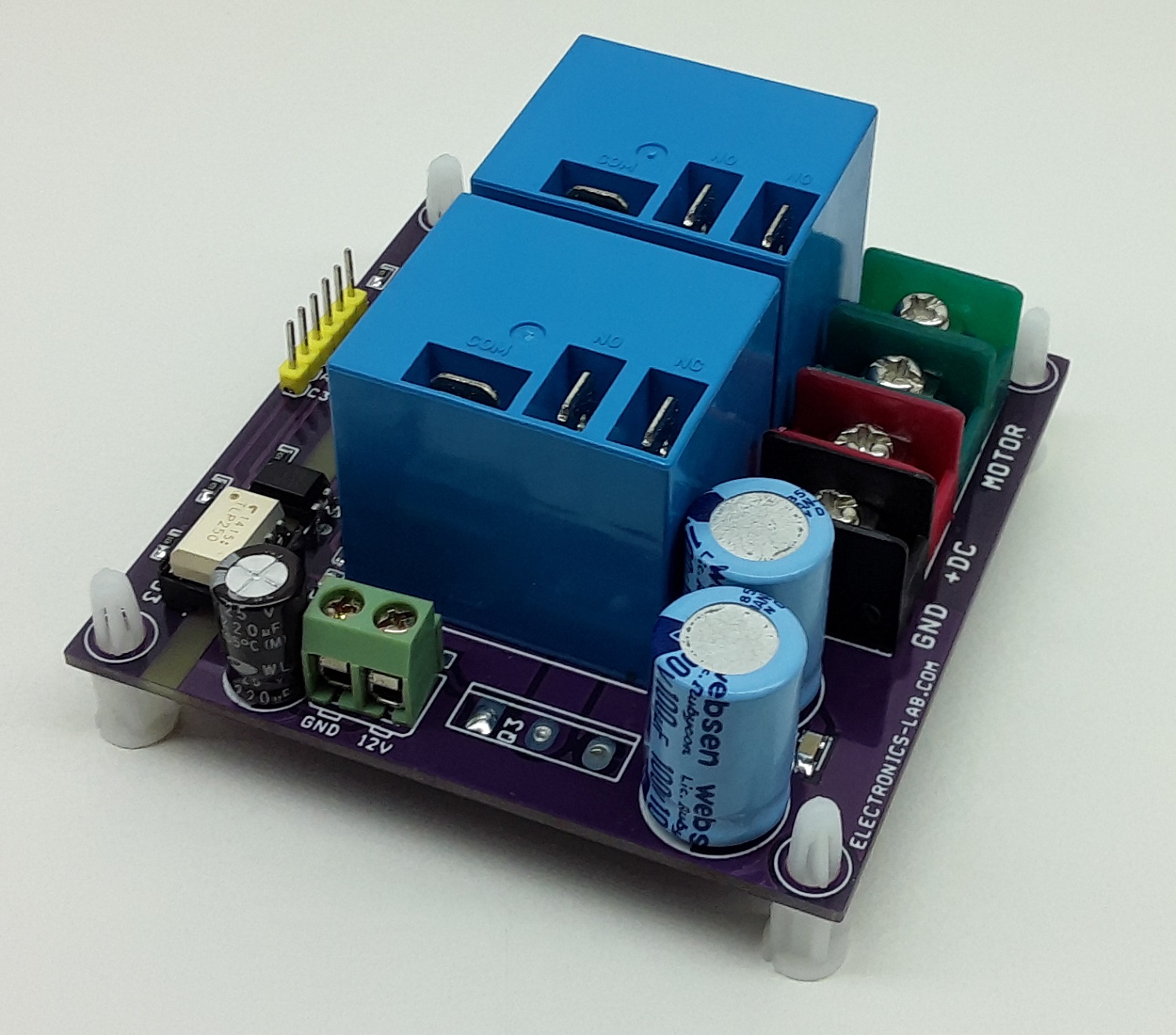
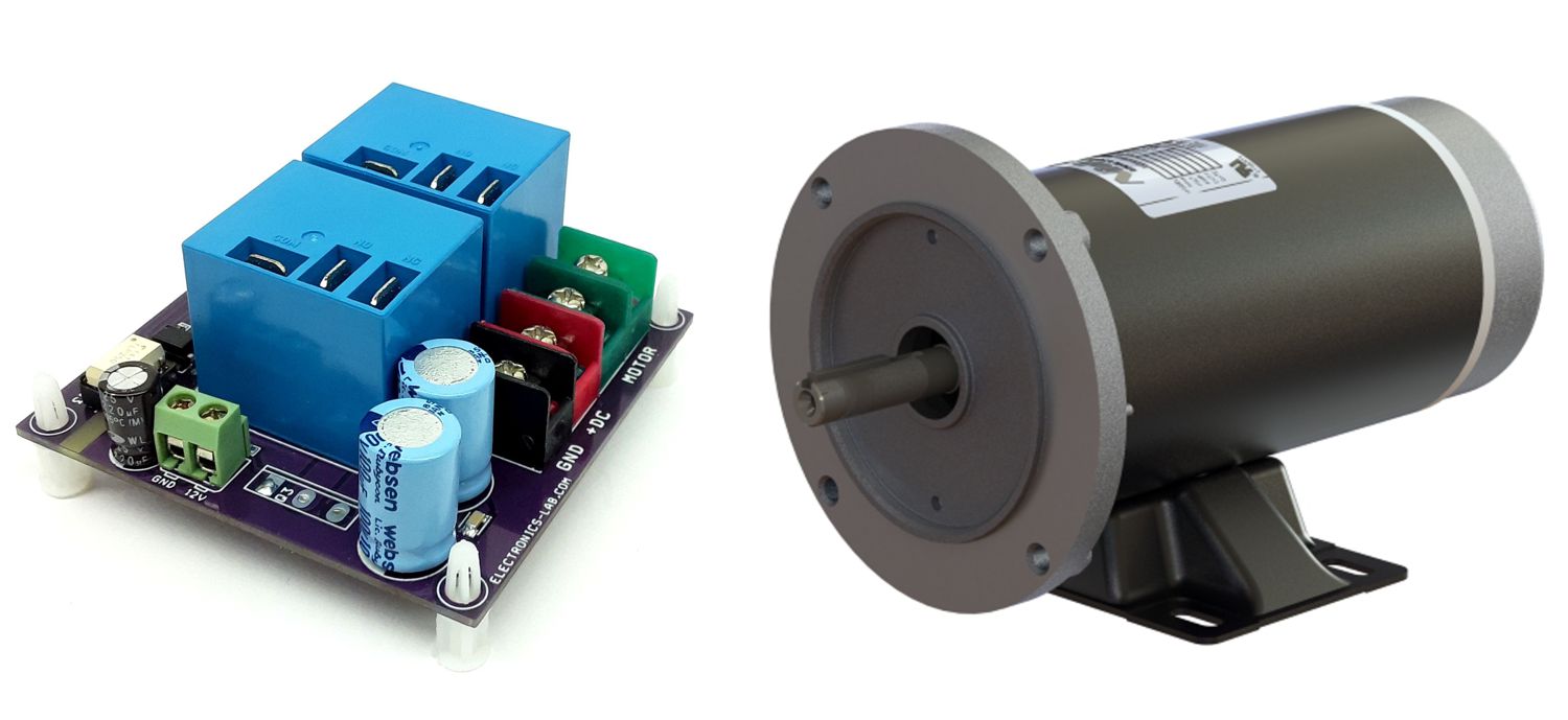
The project presented here is a low-cost solution to control high power brushed DC motor speed and direction. Traditional DC motor controllers are based on solid-state circuitry known as H-Bridge. Here we have made an H-bridge configuration using high current 2 x relays which can handle high voltage as well as high current. Additional MOSFETs are used to control the speed of motor. These MOSFETs can be removed in case of only direction control required, short the Drain and source pin of MOSFETs. The project requires 3 control input signals, all inputs are optically isolated to prevent noise and high voltage going in to logic circuitry. A large-size heatsink is a must on MOSFET.
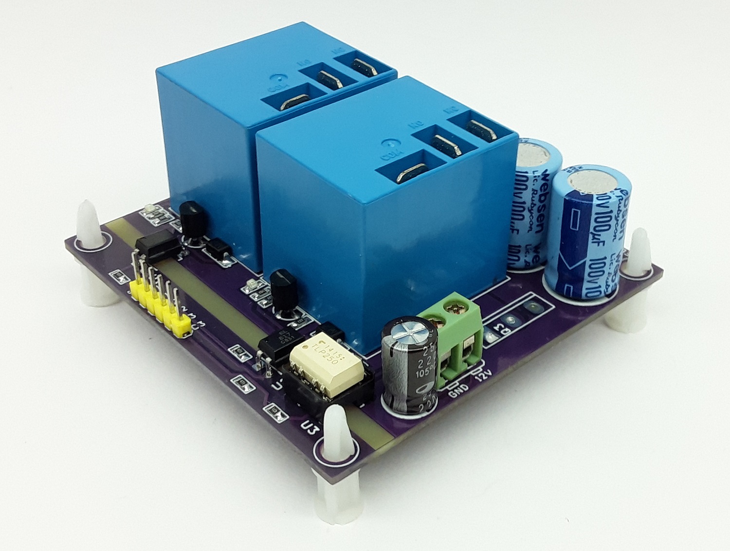
The project requires 3 input signals, 2 x TTL 3V to 5V for direction control and one PWM 0 to 100% Duty Cycle for speed control. Operating supply is 12V DC for logic circuit and relay, Motor supply 12V to 90V DC, Load up to 20A.
Arduino Code
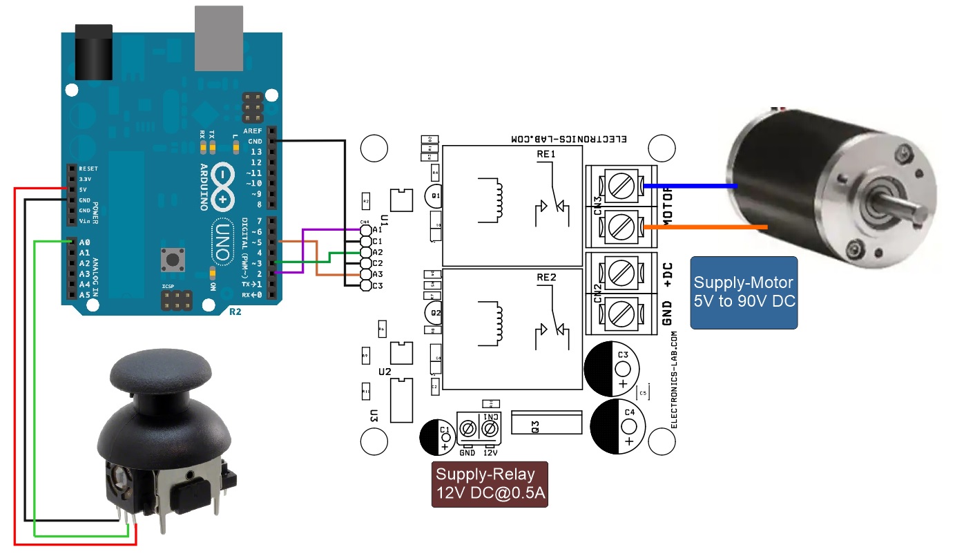
Example Arduino code is provided to test the board. Arduino Uno or Nano is the right choice, refer to the details below for the interface.
- Arduino Pin D4 = CN4 Pin 1 – A1 (DIR 1)
- Arduino Pin D3 = CN4 Pin 3 – A2 (DIR 2)
- Arduino Pin D5= CN4 Pin 5 – A3 (PWM)
- Arduino GND = CN4 Pin 2,4,6 (C1, C2, C3 cathode of Optocouplers)
- Arduino A0 = Joystick or Potentiometer
Input Control Signals (Connect all 3 x Cathode C1, C2, C3 to GND of Arduino) Connector CN4
- DC Motor Forward >> A1 High(3-5V), A2 Low (GND) or Floating, A3 PWM Signal, Duty Cycle 0 to 100%
- DC Motor Reverse >> A1 Low (GND) or Floating, A2 High (3-5V), A3 PWM Signal, Duty Cycle 0 to 100%
Features
- Power Supply for Relay and MOSFET 12V DC @ 100mA
- Power Supply Motor 12V to 90V DC
- Motor Load 20A (Maximum 30A)
- All Inputs are Optically isolated
- 2 x Inputs for Direction Control and Brake
- One PWM Signal to Control the speed of Motor 0 to 100 % Duty Cycle
- PWM Frequency 300Hz to 20 Khz
- 2 x LEDs for direction indication
- PCB dimensions: 75.41 x 74.30 mm
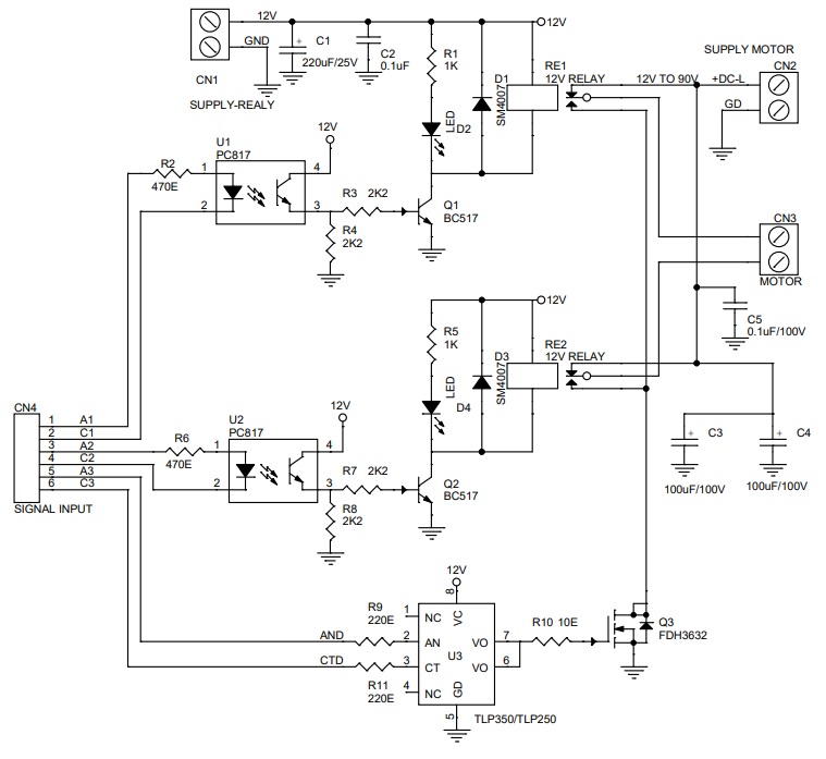
Schematic
Parts List
| NO | QNTY | REF | DESC | MANUFACTURER | SUPPLIER | PART NO |
|---|---|---|---|---|---|---|
| 1 | 1 | CN1 | 2 PIN SCREW TERMINAL PITCH 5.08MM | PHOENIX | DIGIKEY | 277-1247-ND |
| 2 | 1 | CN2 | 2 PIN BARRIER CONNECTOR PITCH 9.53MM | TE CONNECTIVITY | DIGIKEY | 1437664-6-ND |
| 3 | 1 | CN3 | 2 PIN BARRIER CONNECTOR PITCH 9.53MM | TE CONNECTIVITY | DIGIKEY | 1437664-6-ND |
| 4 | 1 | CN4 | 6 PIN MALE HEADER PITCH 2.54MM | WURTH | DIGIKEY | 732-5319-ND |
| 5 | 1 | C1 | 220uF/25V | RUBYCON | DIGIKEY | 1189-3720-3-ND |
| 6 | 1 | C2 | 0.1uF/50V SMD SIZE 0805 | MURATA/YAGEO | DIGIKEY | |
| 7 | 2 | C3,C4 | 100uF/100V | NICHICON | DIGIKEY | 493-13184-3-ND |
| 8 | 1 | C5 | 0.1uF/100V | KYOCERA | DIGIKEY | 478-6107-1-ND |
| 9 | 2 | D1,D3 | SM4007 | SMC DIODE | DIGIKEY | 1655-1N4007FLCT-ND |
| 10 | 1 | D2 | RED LED | LITE ON INC | DIGIKEY | 160-1427-1-ND |
| 11 | 1 | D4 | RED LED | LITE ON INC | DIGIKEY | 160-1427-1-ND |
| 12 | 2 | Q1,Q2 | BC517 | ONSEMI | DIGIKEY | BC517OS-ND |
| 13 | 1 | Q3 | FDH3632 | ONSEMI | DIGIKEY | FDH3632FS-ND |
| 14 | 2 | RE1,RE2 | 12V RELAY | GOODSKY/PANASONIC | DIGIKEY | JTV1G-TMP-12V |
| 15 | 2 | R1,R5 | 1K 5% SMD SIZE 0805 | MURATA/YAGEO | DIGIKEY | |
| 16 | 2 | R2,R6 | 470E 5% SMD SIZE 0805 | MURATA/YAGEO | DIGIKEY | |
| 17 | 4 | R3,R4,R7,R8 | 2K2 5% SMD SIZE 0805 | MURATA/YAGEO | DIGIKEY | |
| 18 | 2 | R9,R11 | 220E SMD SIZE 0805 | MURATA/YAGEO | DIGIKEY | |
| 19 | 1 | R10 | 10E 5% SMD SIZE 0805 | MURATA/YAGEO | DIGIKEY | |
| 20 | 2 | U1,U2 | PC817 | TAIWAN SEMI | DIGIKEY | TPC817BC9G-ND |
| 21 | 1 | U3 | TLP350/TLP250 | TOSHIBA | MOUSER | 757-TLP350HF |
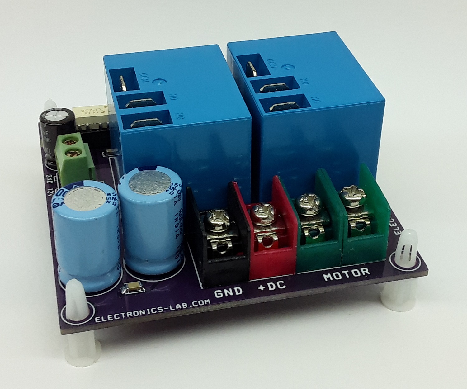
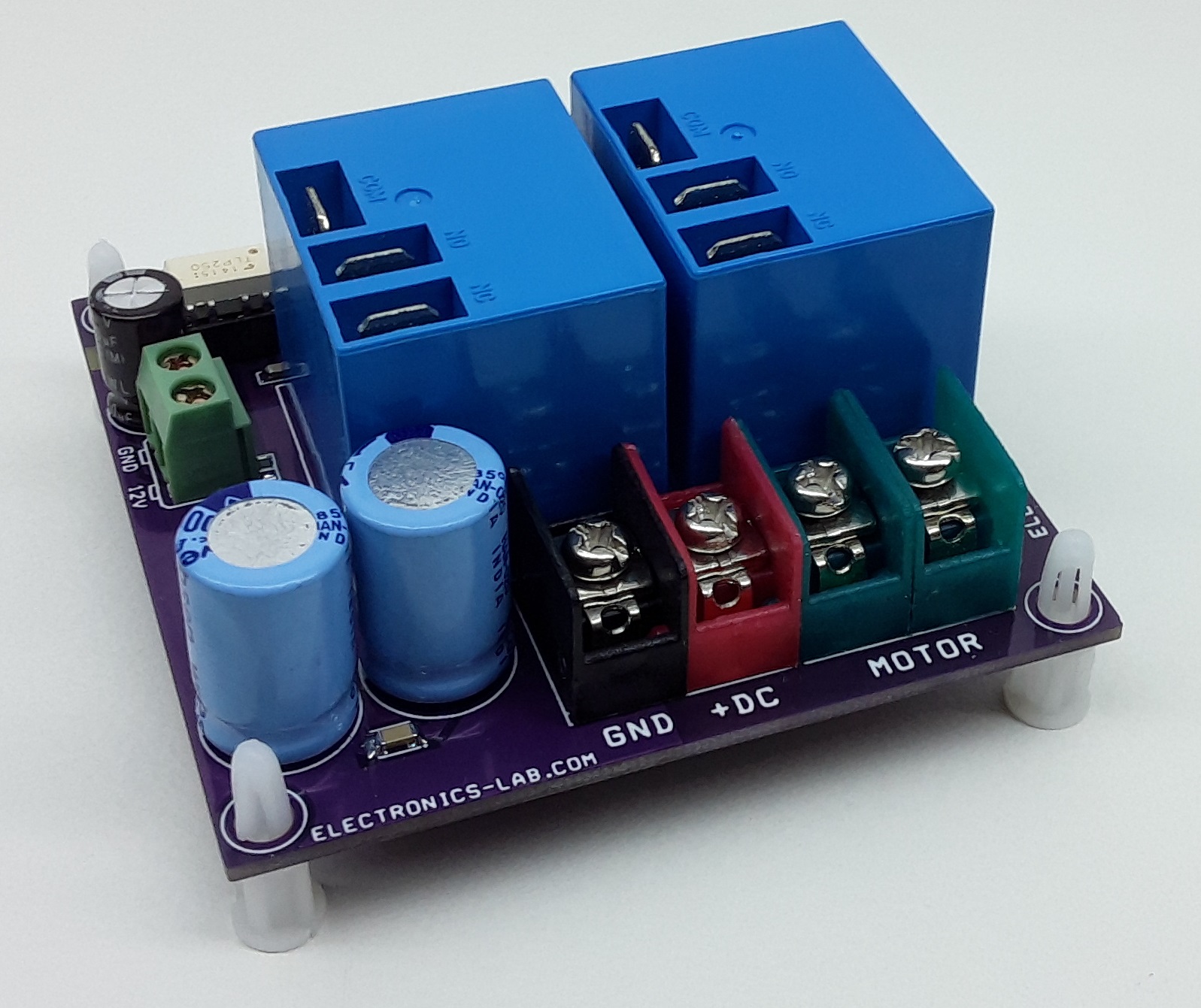
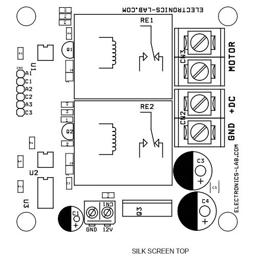
Connections
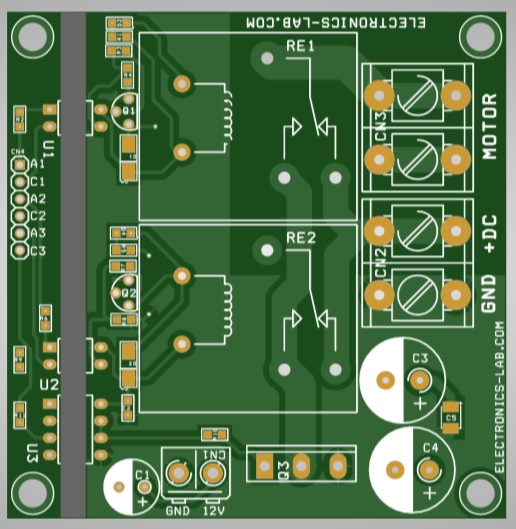
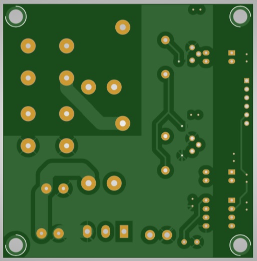
Gerber View
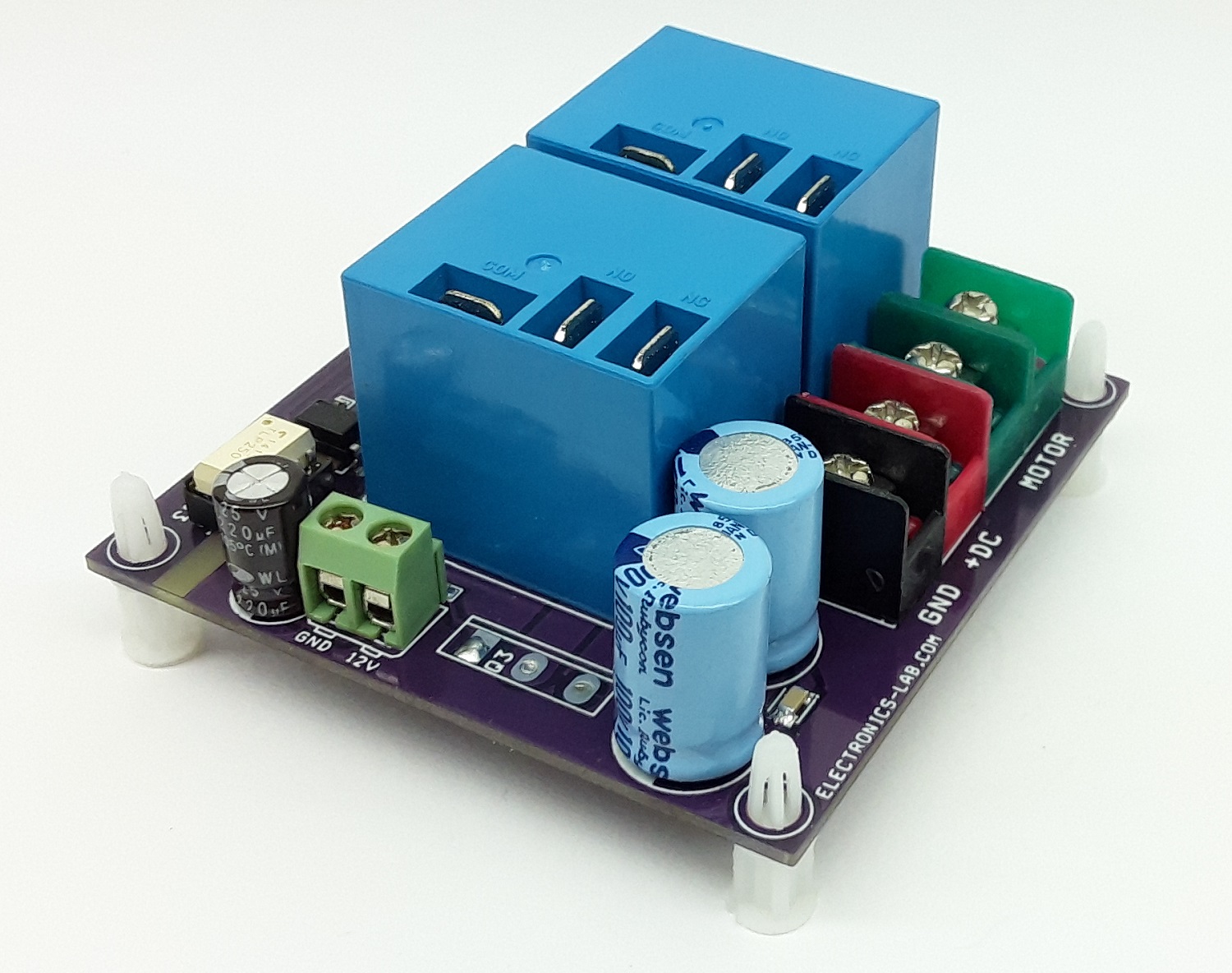
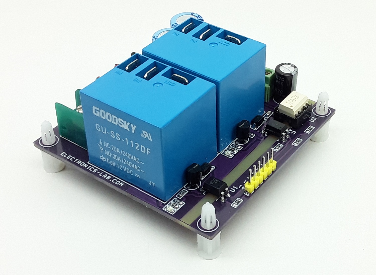
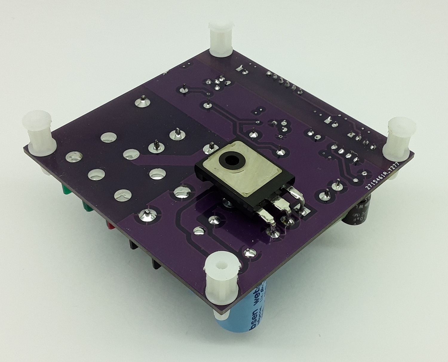
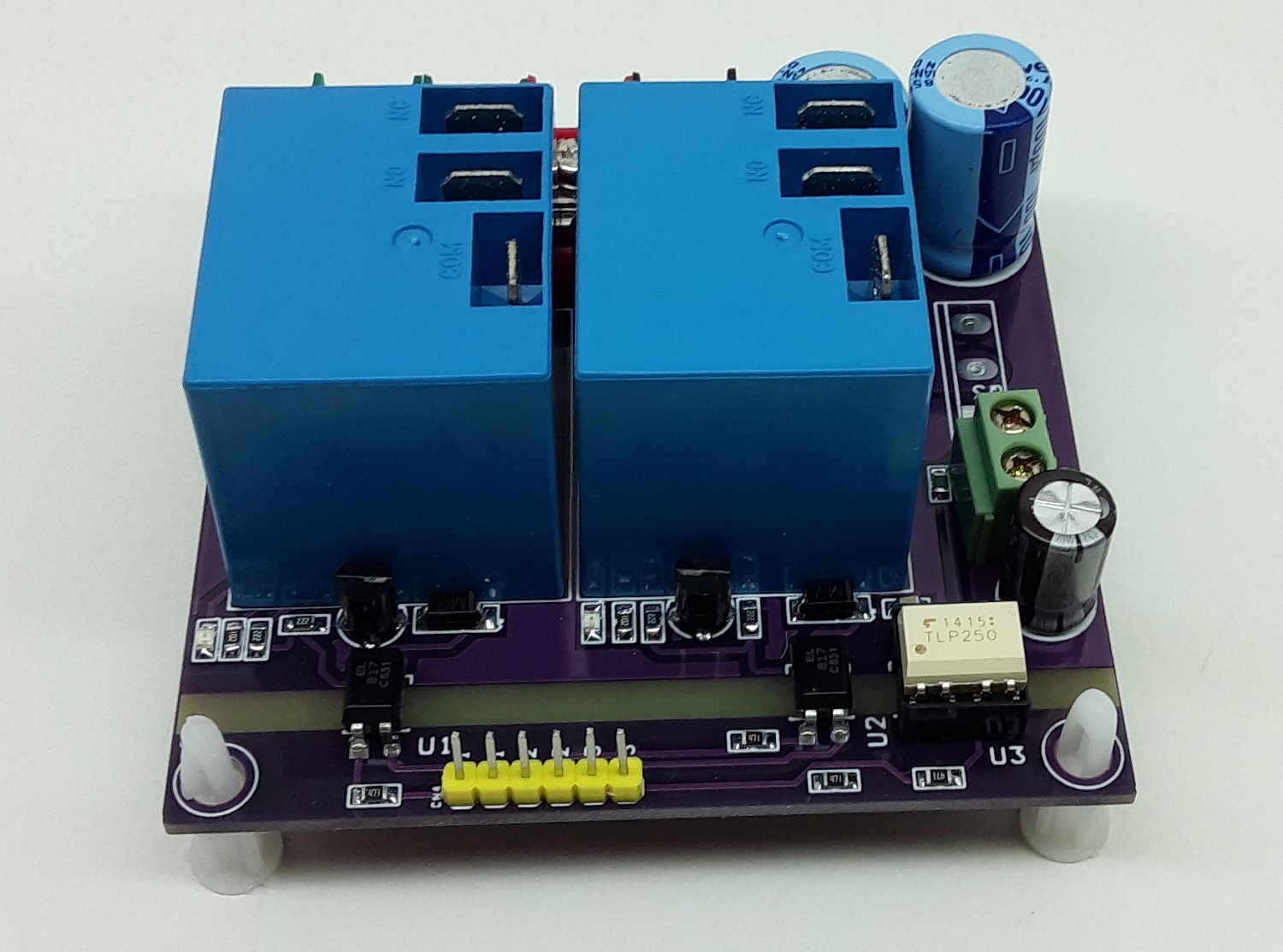
Photos
Video
TLP350 Datasheet
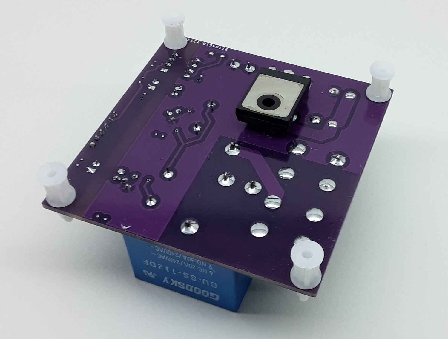
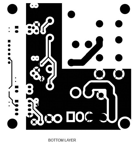
PCB

.png)