Optically Isolated Analog Input Module for Arduino
- Rajkumar Sharma
- 8.239 Views
- easy
- Tested
- SKU: EL101569
- Quote Now
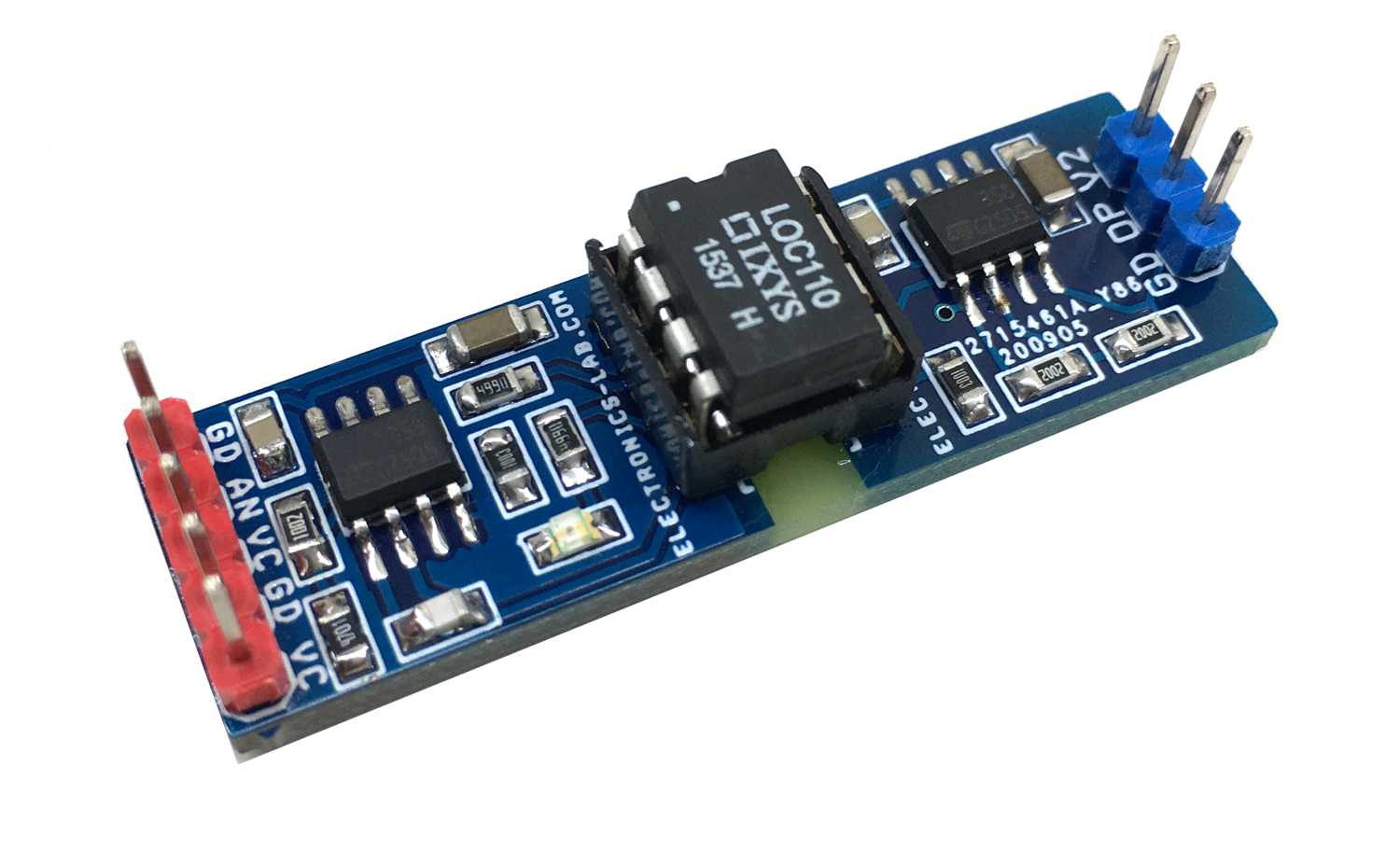
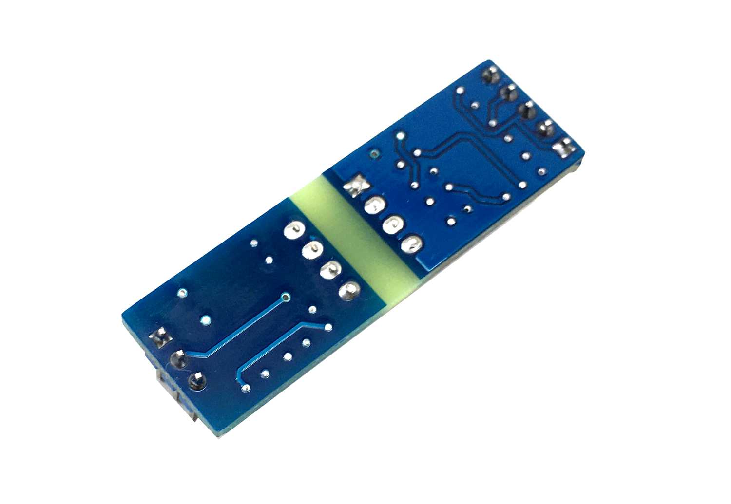
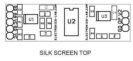
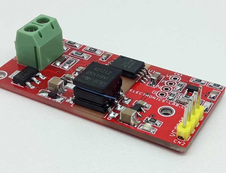
This is an isolated analog input module that is useful for interfacing Analog signals of various types originated from analog sensors and field devices. The module is very useful for in-process controls, factory automation, industrial applications, etc. Interfacing an analog voltage, an analog sensor to Arduino or other various microcontrollers with optical isolation is very easy with this module. The circuit requires two power supplies for the input and output sides. The module takes 0 to 5V analog input and provides optically isolated 0-3.3V as output. The circuit can also be interfaced with a 10V sensor, for 0 to 10V input, change the resistor R3 to 1.8K and the output will be the same 0 to 3.3V. The operating power supply input side and output side is 5V DC. Hook up the sensor or analog voltage to the input of this module and connect the output to Analog Pin of Arduino or ADC of any micro-controller. The circuit is based on an optically isolated linear optocoupler. Isolation voltage between input and output is 3750V. IC1 LM358 is used as a closed-loop servomechanism to sense the photodiode current and drive the LED of the optocoupler. IC2 is a linear optocoupler and IC3 LM358 is a signal conditioner for the phototransistor. D1 is the power LED for the input side supply.
The LOC110 Single Linear Optocoupler features an infrared LED optically coupled with two photodiodes. One feedback (input) photodiode is used to generate a control signal that provides a servomechanism to the LED drive current, thus compensating for the LED’s nonlinear time and temperature characteristics. The other (output) photodiode provides an output signal that is linear with respect to the servo LED current. The IC features wide bandwidth, high input to output isolation, and excellent servo linearity.
Feature
- Operating power supply for the input side and output side is 5V DC
- Current consumption 10mA
- Analog Signal Input Range 0 to 5V
- For Analog Sensor 0 to 10V, Change R3 to 1.8K Ohms
- Output 0 to 3.3V/ 10mA
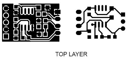
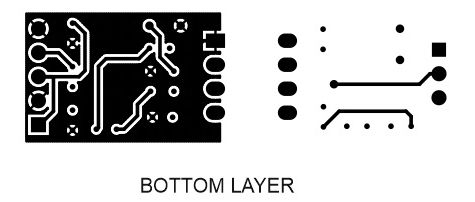
- PCB dimensions: 45.56 x 13.97 mm
Schematic
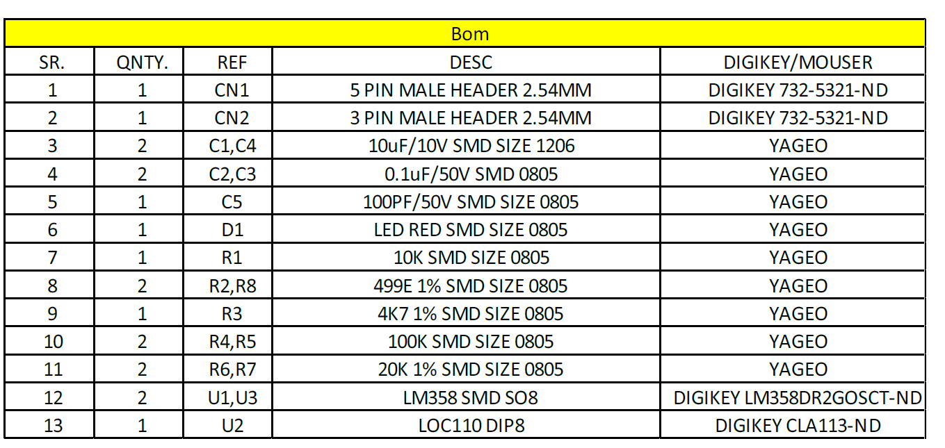
Parts List
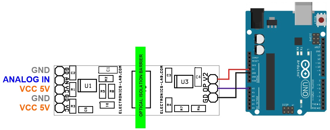
Connections





.png)


Hi, What changes are needed to use the above circuit for measure 4-20ma analog sensors?