

Multiphase Oscillator with 40% Spread Spectrum Frequency Modulation and 250Khz Output Frequency
- Rajkumar Sharma
- 1.066 Views
- easy
- Tested
- SKU: EL107851
- Quote Now
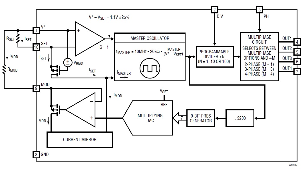
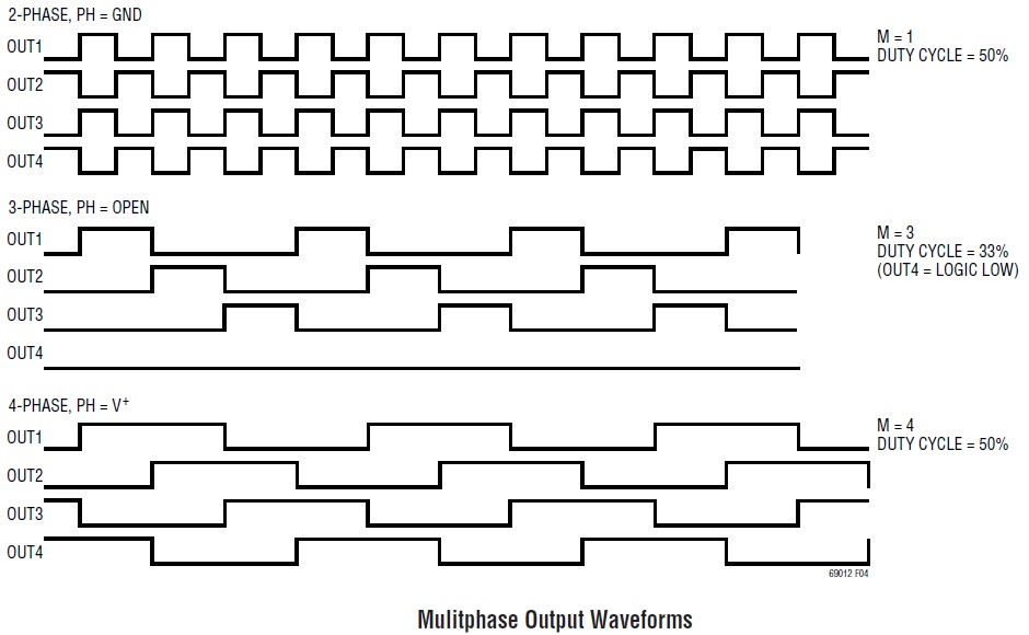
This is a precision, low power, and easy-to-use oscillator that provides multiphase outputs. The output frequency of the project is set to 250Khz, with 40% spread spectrum. The oscillator frequency can be set by resistor R1, and the spread spectrum can be changed using R3. The master oscillator is controlled by the RSET resistor R1 and has a range of 100khz to 20Mhz. In order to accommodate a wider output frequency range, a programable divider, (divide by 1, 10, 100) is included and can be set using jumper J1. The integrated programmable multiphase circuit provides either 2, 3, or 4 phase waveforms. The LTC6902’s SSFM capability modulates the oscillator’s frequency by a pseudorandom noise (PRN) signal to spread the oscillator’s energy over a wide frequency band. This spreading decreases the peak electromagnetic radiation level and improves electromagnetic compatibility (EMC) performance. The amount of frequency spreading is programmable by a single additional external resistor R3 (RMOD). Refer to 4 Phase output waveform diagram.
Features
- Power Input 5V DC
- Default Output Frequency 250Khz
- Default Spread Spectrum 40%
- Jumper for Frequency Division
- Jumper for Multiphase Mode
- 4 Phase Outputs
- PCB Dimensions 20.16 x 15.88 mm
LTC6902 Internal Diagram
Example: 4 Phase, 250Khz Clock with 40% Spreading
- Connect Ph Pin Jumper J2 to VC= Selects 4 Phase Mode, M=4
- Leave Jumper J1 Open N=10 Division
- RSET(R1) =20KOhms Sets F-Out=Fmax=250Khz
- Rmod(R3) =10Kohms Sets the Spreading to 40%
Multiphase Mode, Setting M
- 2-Phase: Connect Jumper2 to GND M=1
- 3-Phase: Leave Jumper J2 Open M=3
- 4-Phase: Connect Jumper J2 to VCC M=4
Choosing Programmable Divider Setting (Frequency Divider Setting Jumper J1)
- Jumper J1 Connect to GND = 2.5Mhz Output Frequency
- Jumper J1 Leave Open = 250khz Output Frequency
- Jumper J1 Connect to VCC = 25Khz Output Frequency
Calculating the RSET Resistor Value
- Maximum Frequency excursion (Fmax) is equal to F-Out.
- RSET(R1) =20Kohms(10Mhz/N*M*F-Out)
- N=100,10,1 (Jumper J1)
- M=4,3,1 (Jumper J2)
Calculating the RMOD Resistor Value
- Rmod=20xRSET/Spreading Percentage
- Where the spreading Percentage is defined by the following:
- Spread Percentage =100xFmax-Fmin/Fmax
- Where Fmax is the highest frequency Excursion (Set by the RSET Value) and Fmin is the lowest frequency excursion
Applications
- Switching Power Supply Clock Reference
- Portable and Battery-Powered Equipment
- PDAs, Cell Phones
- Clocking Switched-Capacitor Filters
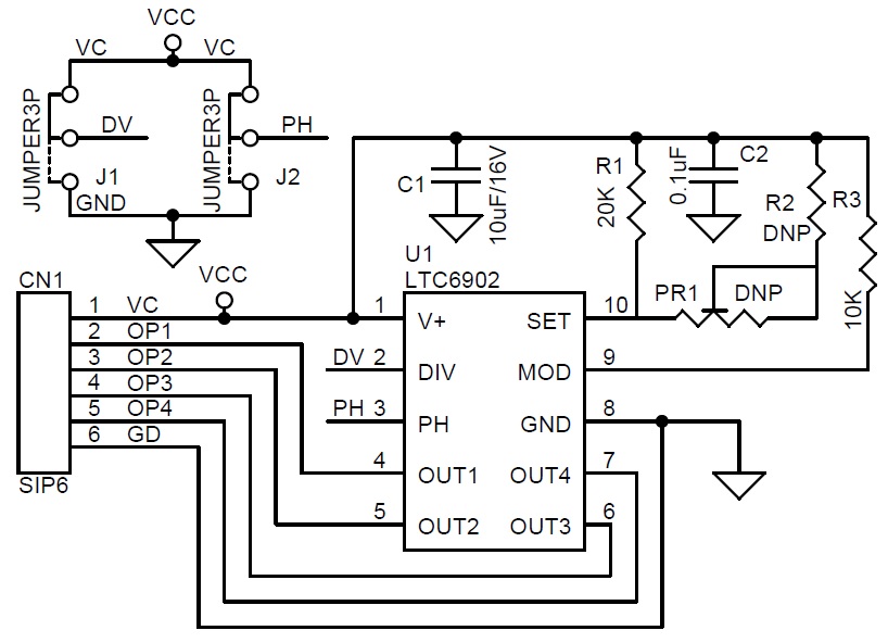
Schematic
Parts List
| NO | QNTY. | REF | DESC. | MANUFACTURER/SUPPLIER |
|---|---|---|---|---|
| 1 | 1 | CN1 | 6 PIN MALE HEADER 2.54MM PITCH | DIGIKEY S1011EC-40-ND |
| 2 | 1 | C1 | 10uF/16V SMD SIZE 1206 | YAGEO |
| 3 | 1 | C2 | 0.1uF/50V SMD SIZE 0805 | YAGEO |
| 4 | 2 | J1,J2 | JUMPER3P/SHUNT 2.54MM | DIGIKEY S9001-ND |
| 5 | 2 | PR1,R2 | DNP | OMIT |
| 6 | 1 | R1 | 20K 1% SMD SIZE 0805 | YAGEO |
| 7 | 1 | R3 | 10K 1% SMD SIZE 0805 | YAGEO |
| 8 | 1 | U1 | LTC6902 | DIGIKEY LTC6902CMS#TRPBFCT-ND |
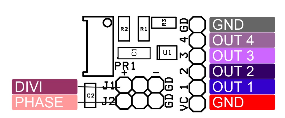
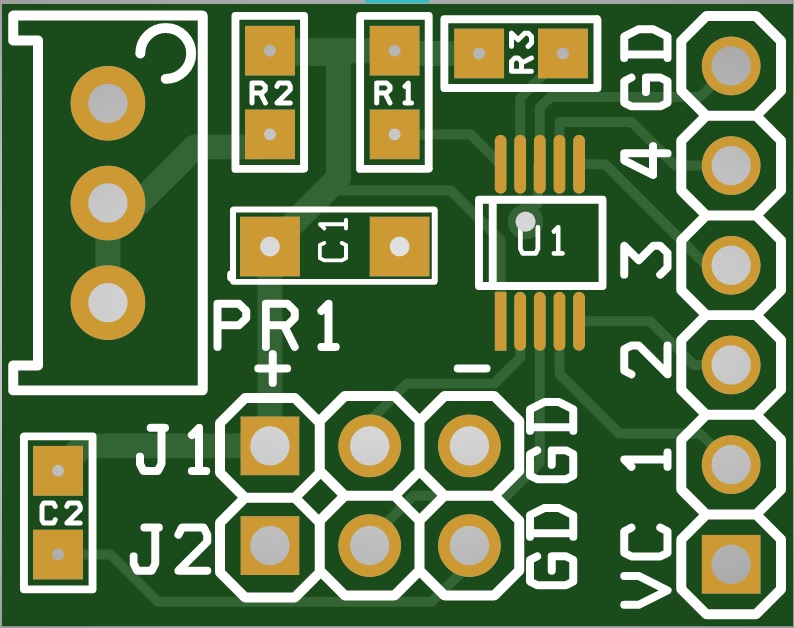
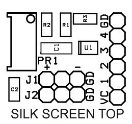
Connections
Output waveforms
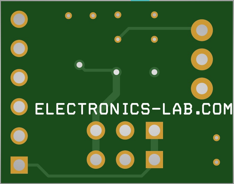
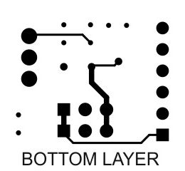
Gerber View
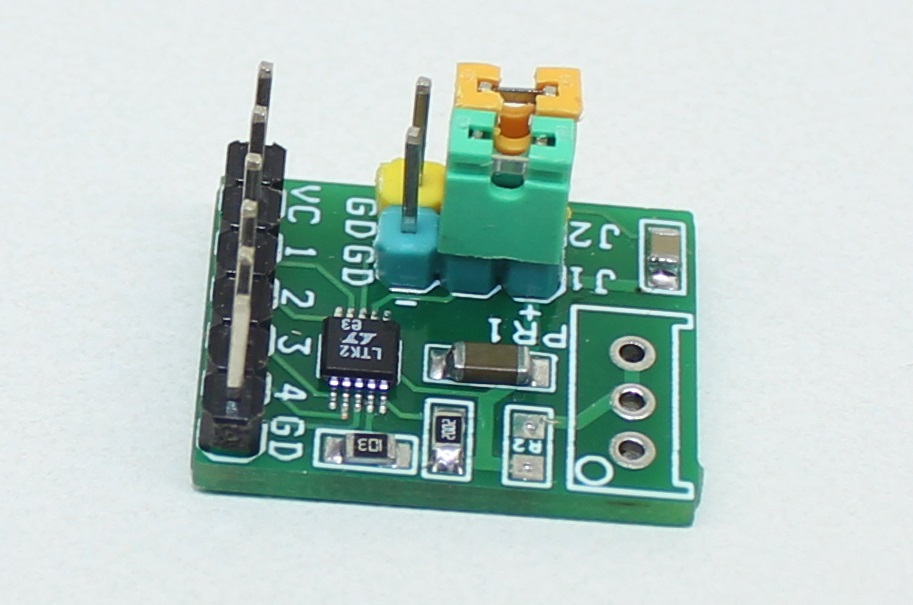
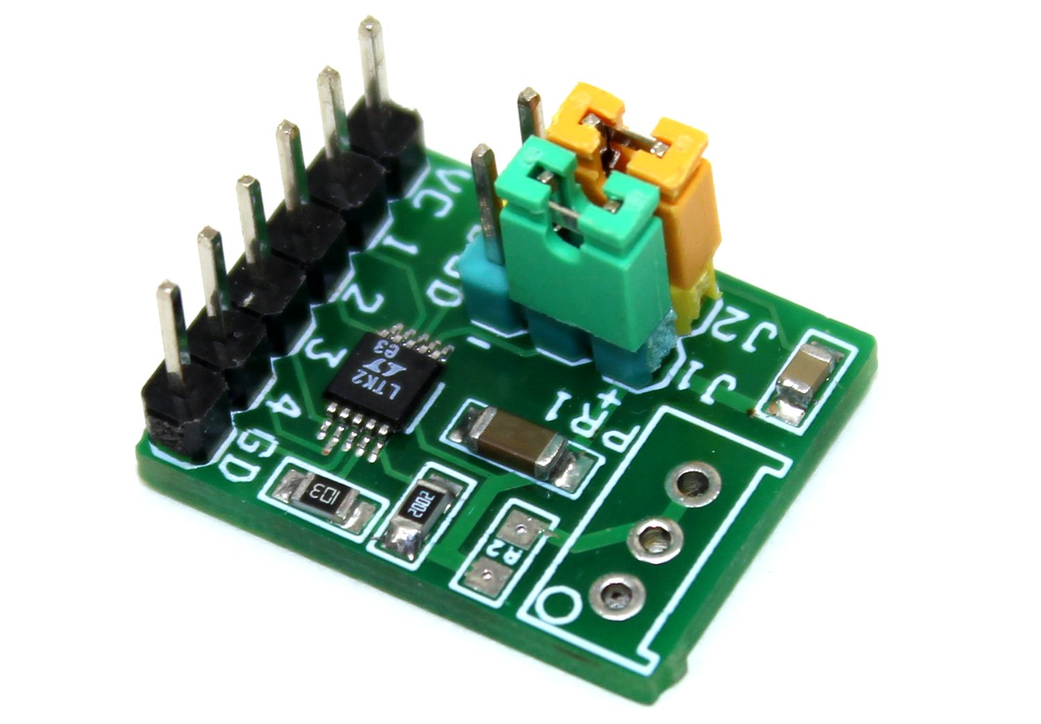
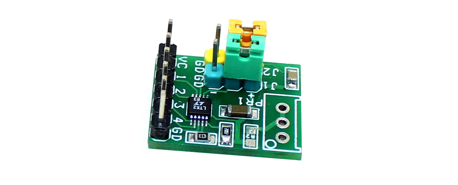
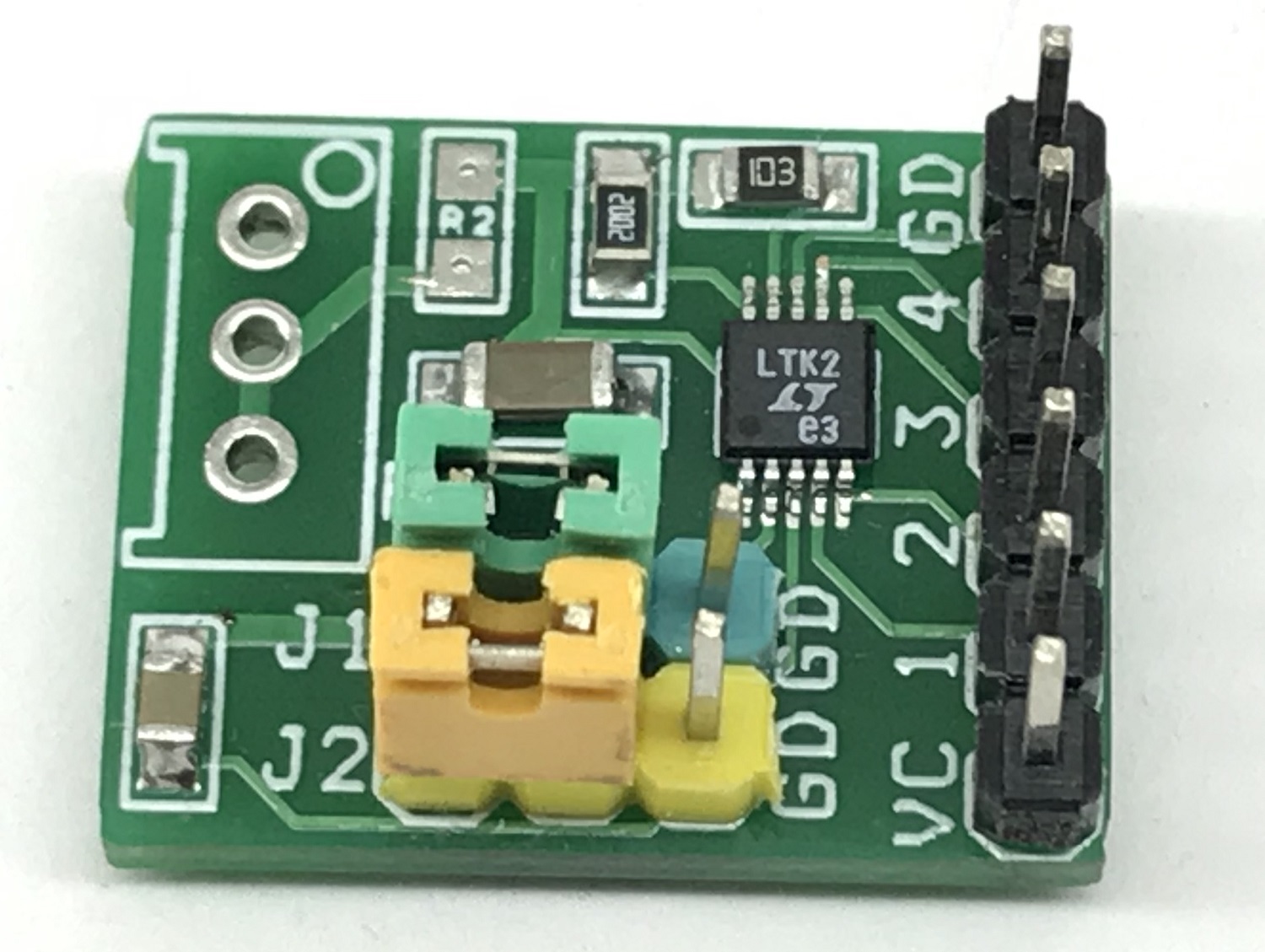
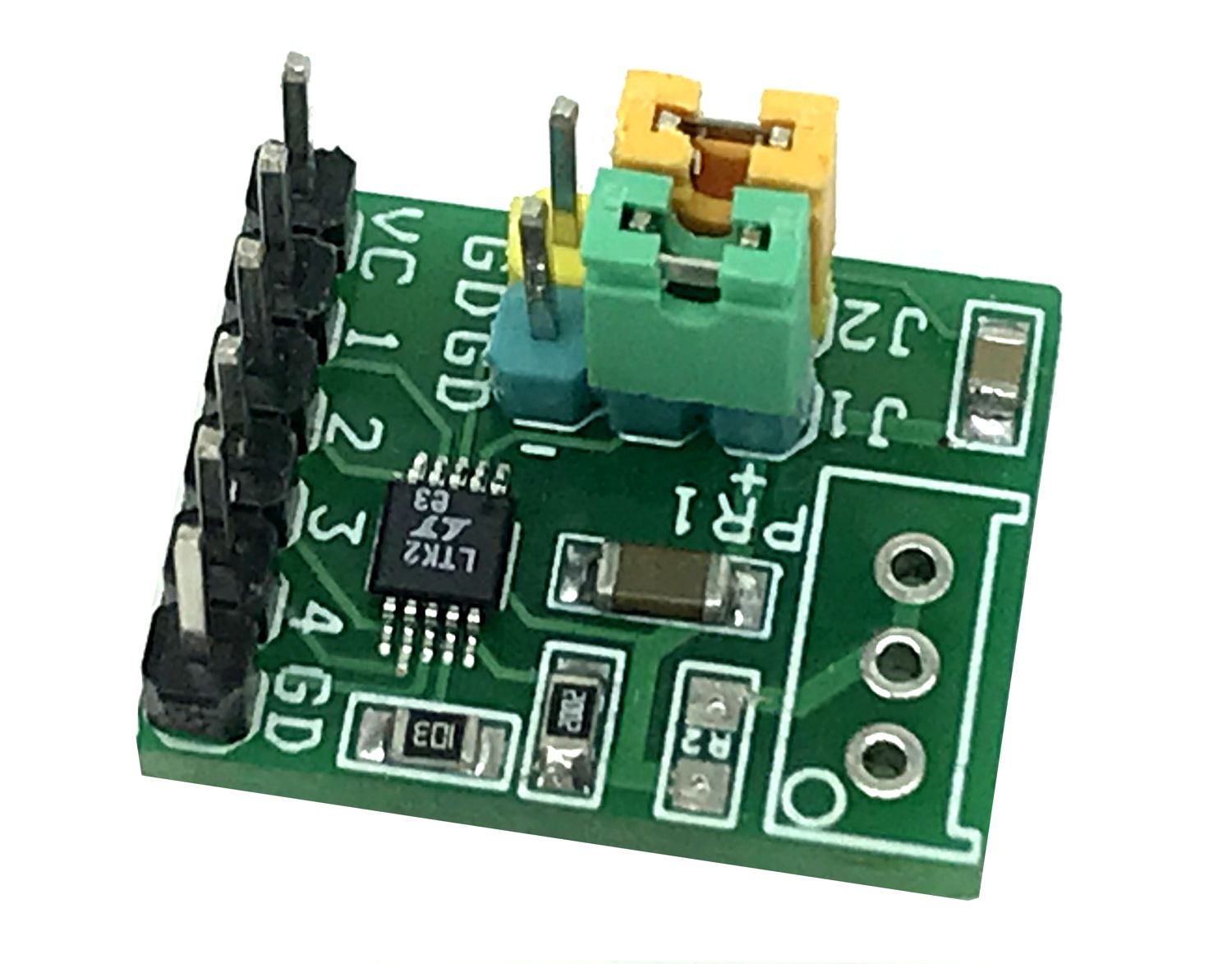
Photos
Video
LTC6902 Datasheet
PCB

.png)


 Audio Power Amplifier")