

1200V High-Current Half-Bridge using FAN73912
- Rajkumar Sharma
- 157 Views
- medium
- Tested
- SKU: EL121045
- Quote Now
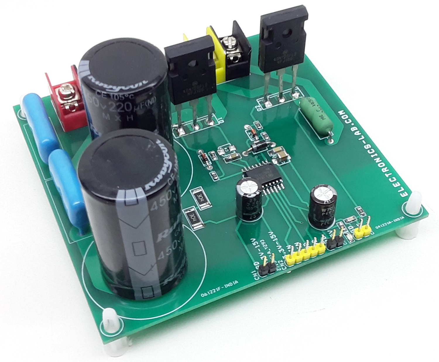
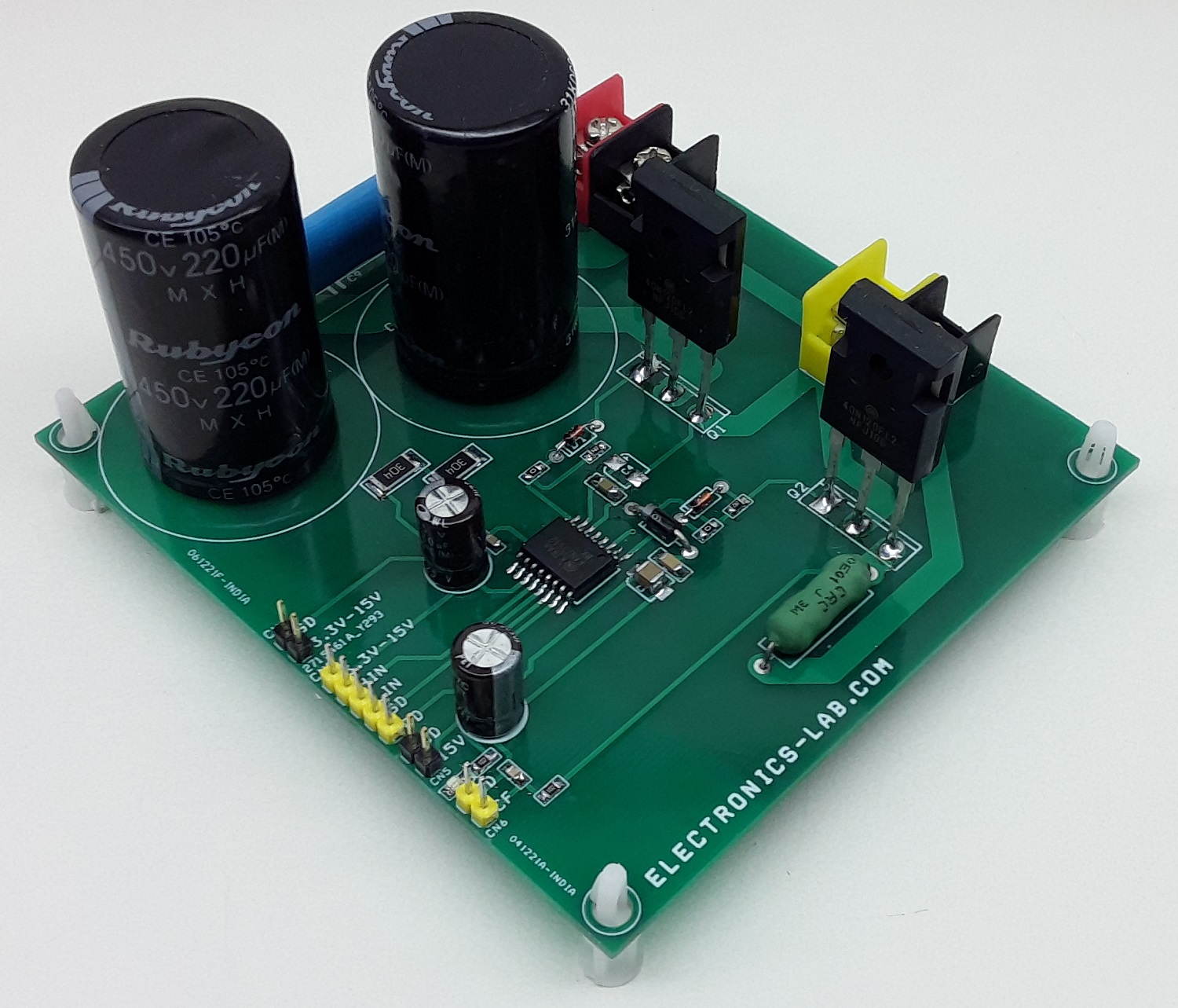
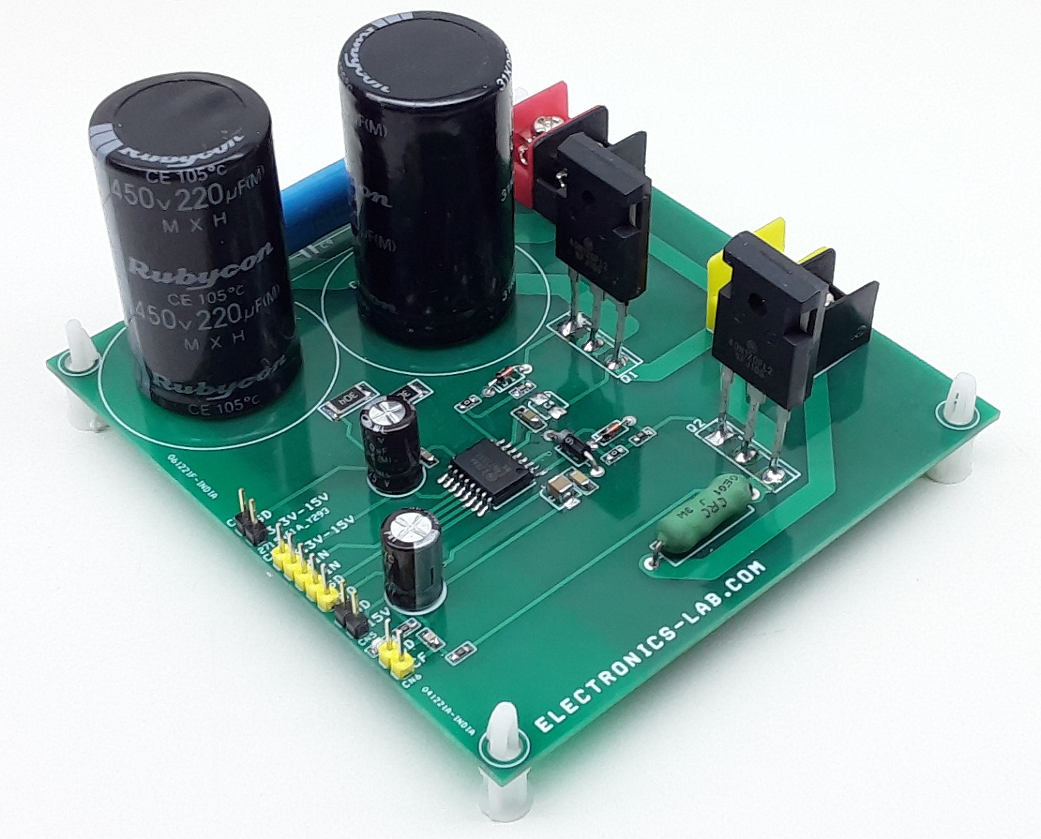
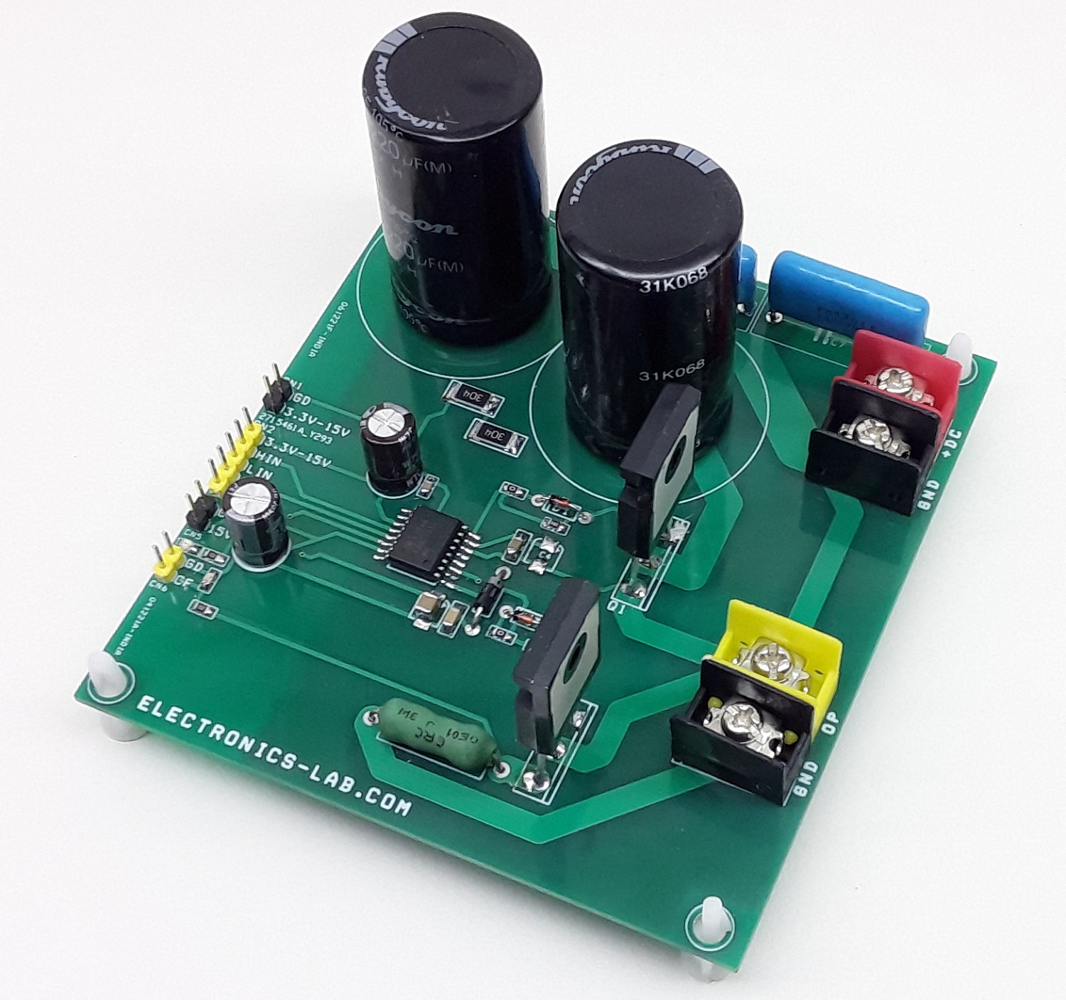
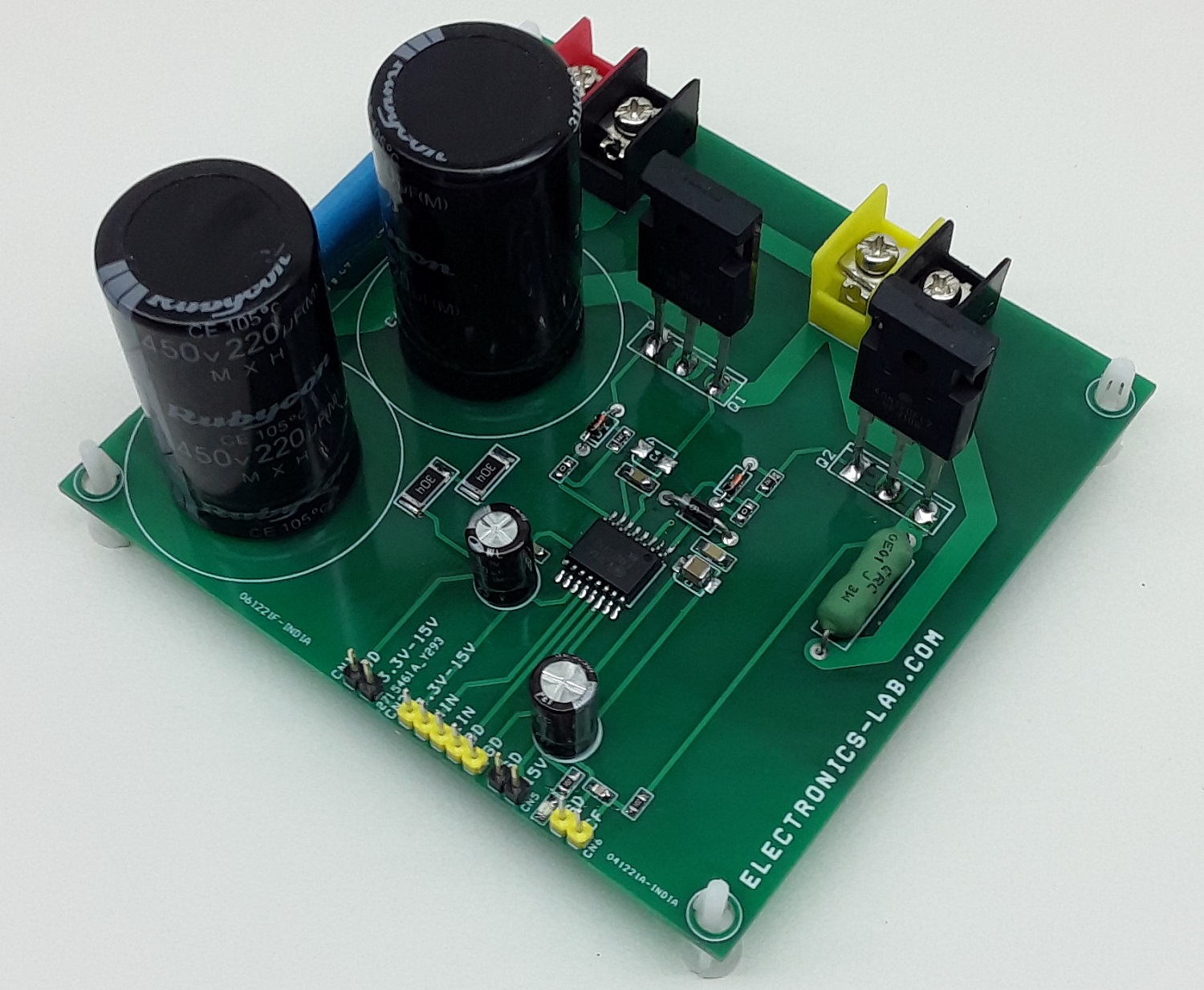
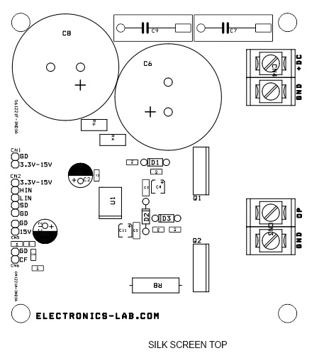
The project presented here is designed for high-voltage and high-speed driving for MOSFETS and IGBTs that operate up to +1200V. The project consists of a FAN73912 gate driver chip and 2 x IGBTs, DC bus capacitors, current sense resistor for current feedback etc. The advanced input filter of HIN provides protection against short-pulsed input signals caused by noise. An advanced level-shift circuit offers high-side gate driver operation up to VS=-9.8 V (typical) for VBS=15 V. The UVLO circuit prevents malfunction when VCC and VBS are lower than the specified threshold voltage. R8 is the current sense resistor.
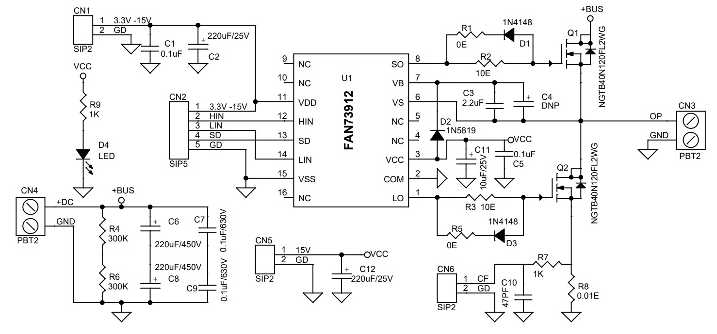
We have tested this board with 1200V/40Amps NGTB40N120FL2WG IGBT. The user may install any other MOSFET or IGBT as per power requirements. The value of resistors R1, R2, R3, R5, and C3 (C4) will depend on MOSFET and IGBT selected. Refer to the datasheet of FAN73912 for more information. Choose DC bus Capacitor C6, C7, C8, C9 as per operating power supply. The FAN73912 Output drivers typically source and sink 2 A and 3 A, respectively. Resistors R4 and R6 are bleeding resistors. D4 power LED for VCC, header connector CN2 for signal inputs.
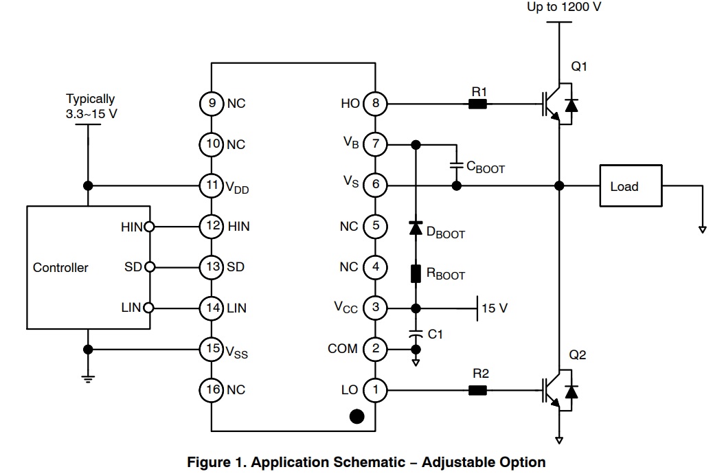
The bootstrap resistor, RBOOT, must be considered in sizing the bootstrap resistance and the current developed during the initial bootstrap charge. If the resistor is needed in series with the bootstrap diode, verify that VB does not fall below COM (ground). Recommended use is typically 5 – 10 Ohms. That increases the VBS time constant. If the voltage drop of the bootstrap resistor and the diode is too high or the circuit topology does not allow a sufficient charging time, a fast recovery or ultra−fast recovery diode can be used.
Features
- Floating Channel for Bootstrap Operation to +1200 V
- Logic Power Supply VDD 3.3V to 15V DC (Range 3V to 20V)
- Gate Driver Power Supply VCC 15V DC (Range 12V to 20V)
- Built-in Cycle-by-Cycle Edge-Triggered Shutdown Logic
- Built-in Shoot-Through Protection Logic
- Common-Mode dv/dt Noise Cancelling Circuit
- UVLO Functions for Both Channels
- Built-in Advanced Input Filter
- Matched Propagation Delay Below 50 ns
- Outputs in-Phase with Input Signal
- Logic and Power Ground +/- 10 V Offset
- UVLO Functions for Both Channels
- On-Board Shunt Resistor for Current Feedback
- PCB Dimensions 99.70 x 106.68 mm
Connections
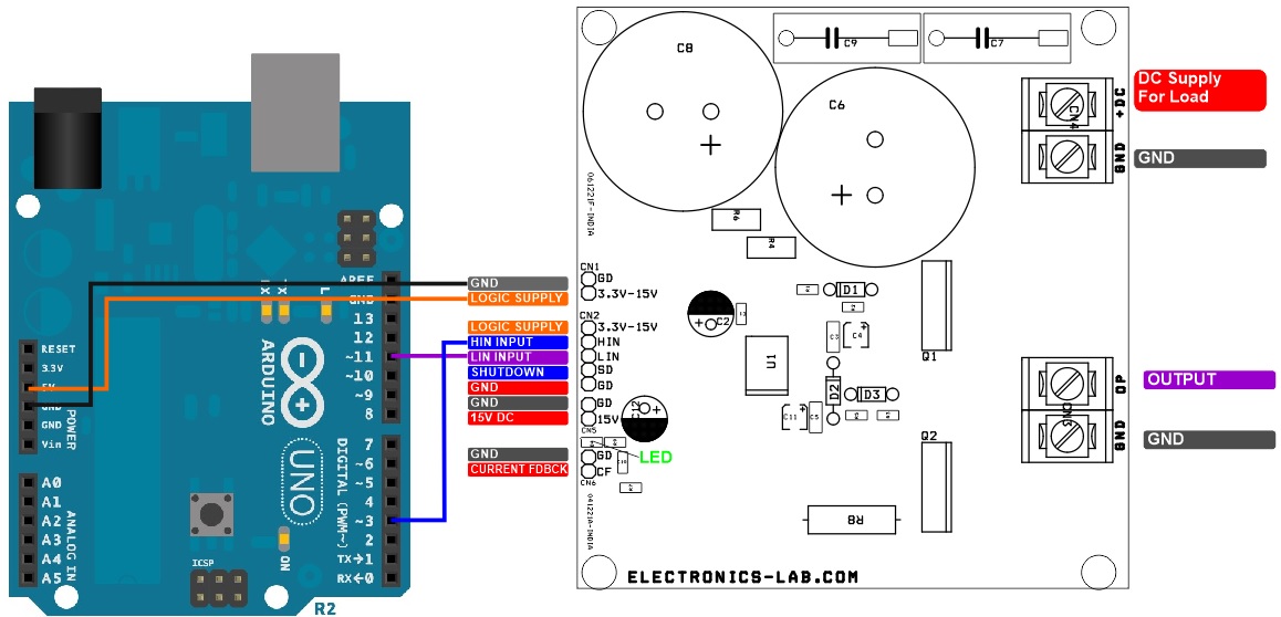
- CN2: Pin 1 = Logic + 3.3V to 15V, Pin 2 = High Input, Pin 3 Low Input, Pin 4= Shutdown (High-in =Shutdown, Low Normal Operation), Pin 5 = GND
- CN1: Pin 1= + 3.3V to 15 V Logic Supply, Pin 2 = GND
- CN3: Pin 1 = OP Load, Pin 2 GND
- CN4: Pin 1= +DC Load Power Supply Input, Pin2= GND
- CN5: Pin 1 = + 15V Gate Driver Power Supply, Pin 2 = GND
- CN6: Pin1= + Current Feed Back Output, Pin 2= GND
Applications
- High Current Resistive and Inductive Loads, Such as Heaters, LED, Lamps, Motors
- Half-Bridge and Full-Bridge Motor Control
- Synchronous Step-Down Switching Regulators
- Three-Phase Brushless Motor Drivers
- High Current Transducer Drivers
- Electrical Contactor
- UPS
- Solar Inverter
- Ballast
- General−Purpose Half−Bridge Topology
Arduino Code
This board can be tested using Arduino. Example code is provided for testing purposes. This code provides 20KHz Dual Output, Phase shift 180 Degrees, 50% duty cycle.
Credits: The author of the Arduino Code is Ted Burke. More information on his website: https://batchloaf.wordpress.com/2018/04/27/h-bridge-control-example-for-arduino-nano-atmega328-2-phase-displaced-square-waves/
Schematic
Parts List
| NO | QNTY | REF | DESC. | MANUFACTURER | SUPPLIER | PART NO |
|---|---|---|---|---|---|---|
| 1 | 3 | CN1,CN5,CN6 | 2 PIN MALE HEADER PITCH 2.54MM | WURTH | DIGIKEY | 732-5315-ND |
| 2 | 1 | CN2 | 5 PIN MALE HEADER PITCH 2.54MM | WURTH | DIGIKEY | 732-5318-ND |
| 3 | 2 | CN3,CN4 | 2 PIN BARRIER CONNECTOR PITCH 9.53MM | TE CONNECTIVITY | DIGIKEY | 1437664-6-ND |
| 4 | 2 | C1,C5 | 0.1uF/50V SMD SIZE 0805 | MURATA/YAGEO | DIGIKEY | |
| 5 | 2 | C2,C12 | 220uF/25V | RUBYCON | DIGIKEY | 1189-3720-1-ND |
| 6 | 1 | C3 | 2.2uF/25V SMD SIZE 1206 | MURATA/YAGEO | DIGIKEY | |
| 7 | 1 | C4 | DNP | DO NOT INSTALL | ||
| 8 | 2 | C6,C8 | 220uF/450V | RUBYCON | DIGIKEY | 1189-2034-ND |
| 9 | 2 | C7, C9 | 0.1uF/630V | RUBYCON | DIGIKEY | 1189-1836-ND |
| 10 | 1 | C10 | 47PF/50V | MURATA/YAGEO | DIGIKEY | |
| 11 | 1 | C11 | 10uF/25V | MURATA/YAGEO | DIGIKEY | |
| 12 | 2 | D1,D3 | 1N4148 | ON SEMI | DIGIKEY | 1N4148FS-ND |
| 13 | 1 | D2 | 1N5819 | ON SEMI | DIGIKEY | 1N5819GOS-ND |
| 14 | 1 | D4 | LED | LITE ON INC | DIGIKEY | 160-1427-1-ND |
| 15 | 2 | Q1,Q2 | NGTB40N120FL2WG | ON SEMI | DIGIKEY | NGTB40N120FL2WGOS-ND |
| 16 | 2 | R1,R5 | 0E SMD SIZE 0805 | MURATA/YAGEO | DIGIKEY | |
| 17 | 2 | R2,R3 | 10E 5% SMD SIZE 0805 | MURATA/YAGEO | DIGIKEY | |
| 18 | 2 | R4,R6 | 300K 5% SMD SIZE 2512 | STAKEPOLE | DIGIKEY | RMCF2512JT300KCT-ND |
| 19 | 2 | R7,R9 | 1K 5% SMD SIZE 0805 | MURATA/YAGEO | DIGIKEY | |
| 20 | 1 | R8 | 0.01E/3W | OHMLITE | DIGIKEY | 13FR010E-ND |
| 21 | 1 | U1 | FAN73912 | ON SEMI | DIGIKEY | FAN73912MXCT-ND |
Connections
Typical Application
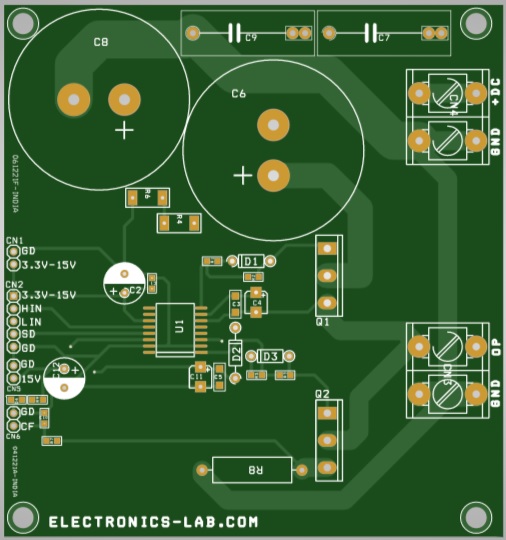
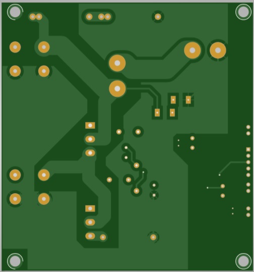
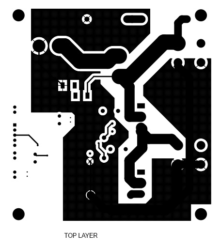
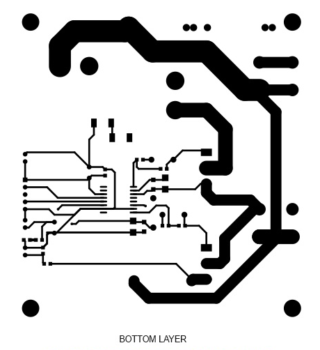
Gerber View
Photos
Video
FAN73912 Datasheet
PCB
.png)


")