
Current Meter Using 0.96″ OLED Display
- Rajkumar Sharma
- 3.145 Views
- moderate
- Tested
- SKU: EL101933
- Quote Now
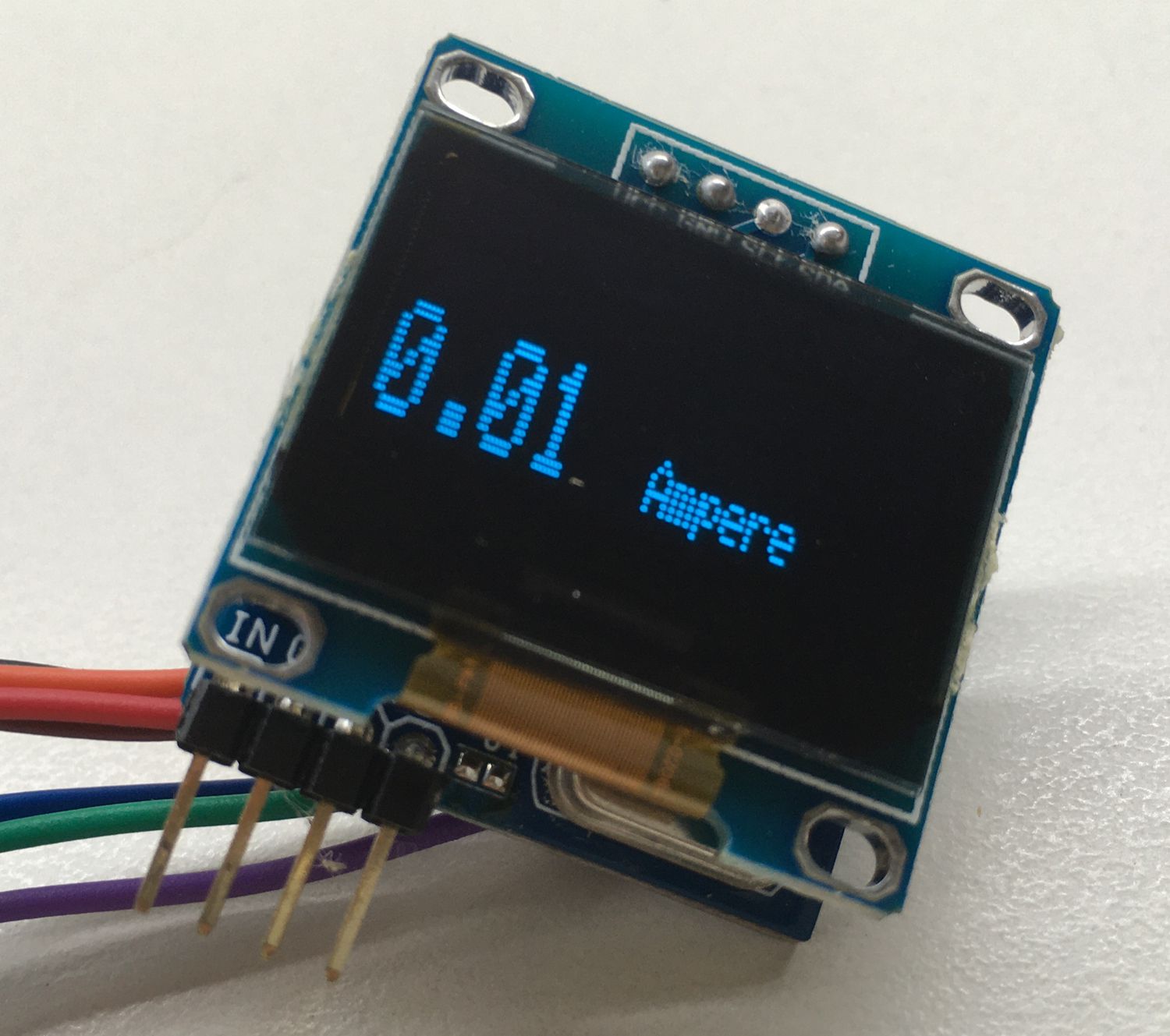
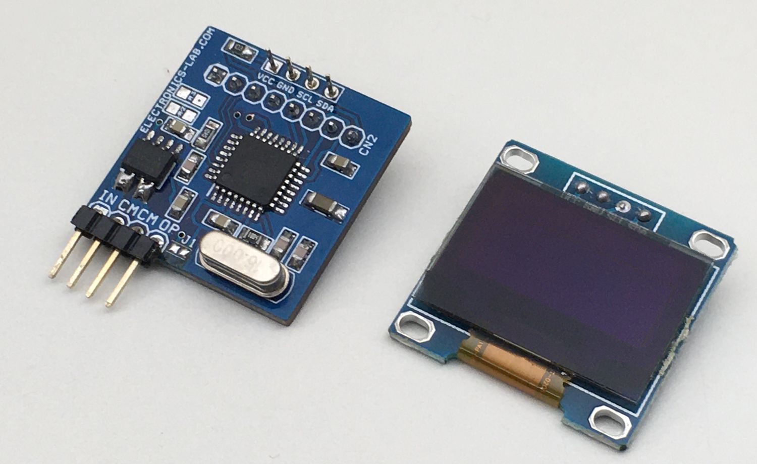
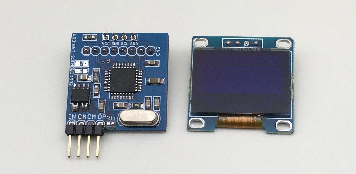
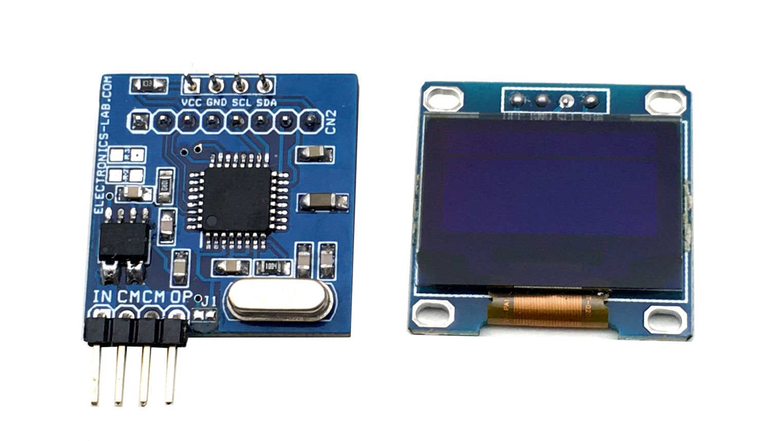
This project provides an economical and precise solution for DC current sensing and display on an OLED display. This board uses the ACS715T-20A hall effect-based linear current sensor chip, 0.96 Inch I2C OLED Display and Atmega328 microcontroller chip. It is an Arduino compatible open-source hardware that can be modified to your requirements. It is easily programable using the Arduino IDE. Connector CN2 is provided for Boot-Loader burning and programming of the Atmega328 chip using Arduino IDE. Refer to the wiring diagram below for programming and connections. The board can measure current up to 20A DC. Operating power supply 5V DC and it consumes approx. 20mA current.
ACS715 device consists of a precise, low-offset, linear Hall circuit with a copper conduction path located near the surface of the die. Applied current flowing through this copper conduction path generates a magnetic field which the Hall IC converts into a proportional voltage. Device accuracy is optimized through the close proximity of the magnetic signal to the Hall transducer. A precise, proportional voltage is provided by the low-offset, chopper-stabilized Bi-CMOS Hall IC, which is programmed for accuracy after packaging. The output of the device has a positive slope (>VIOUT(Q)) when an increasing current flows through the primary copper conduction path (from pins 1 and 2, to pins 3 and 4), which is the path used for current sampling. The internal resistance of this conductive path is 1.2 mΩ typical, providing low power loss. The thickness of the copper conductor allows survival of the device at up to 5× overcurrent conditions. The terminals of the conductive path are electrically isolated from the signal leads (pins 5 through 8). This allows the ACS715 to be used in applications requiring electrical isolation without the use of optoisolators or other costly isolation techniques.
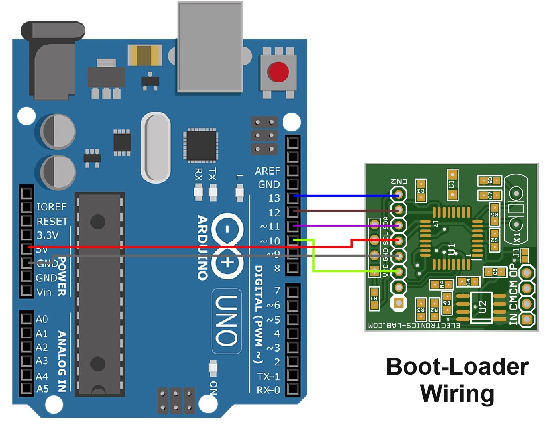
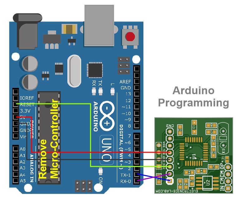
Boot-Loader Burning & Arduino Programming
A new ATmega328 chip requires Boot-Loader burning and programming. The links below will help you to understand the process.
- Burning Arduino Bootloader on ATMega328 using USBasp Programmer – https://www.electronics-lab.com/burning-the-bootloader-on-atmega328-using-usbasp-programmer/
- Flashing Arduino Bootloader on Atmega328p Microcontroller – https://www.electronics-lab.com/project/installing-the-arduino-bootloader-on-the-atmega328p-microcontroller/
- Programming Atmega328p Microcontroller with Arduino IDE – https://www.electronics-lab.com/project/programming-atmega328p-microcontroller-with-arduino-ide/
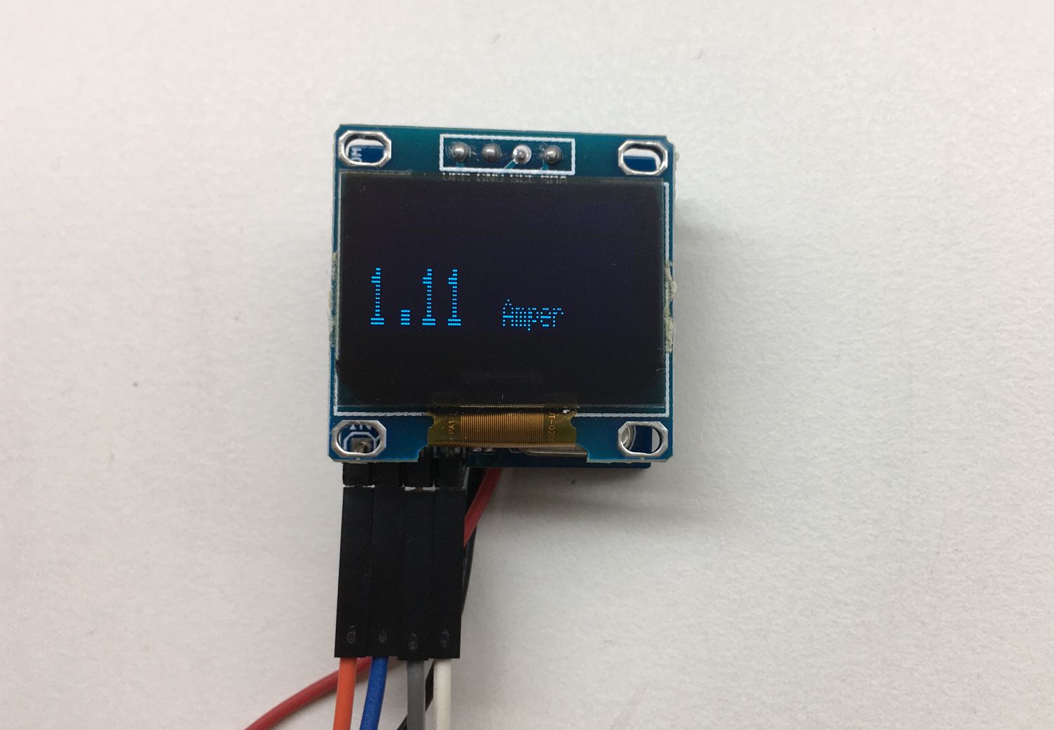
Example Arduino code is provided under the download section. This code will help you to test the project, we have tested with current up to 3A.
Features
- Power Supply 5V DC
- Current Consumption 20mA Approx.
- Current Measuring Range 0 to 20Amps (DC Only)
- Sensitivity of ACS715-20A: 185mV/Amp
- 5 µs output rise time in response to step input current
- 80 kHz bandwidth
- Total output error 1.5% typical at TA= 25°C
- Small footprint, low-profile SOIC8 package
- 1.2 mΩ internal conductor resistance
- 2.1 kVRMS minimum isolation voltage from pins 1-4 to pins 5-8
- 5.0 V, single supply operation
- 133 to 185 mV/A output sensitivity
- Output voltage proportional to DC currents
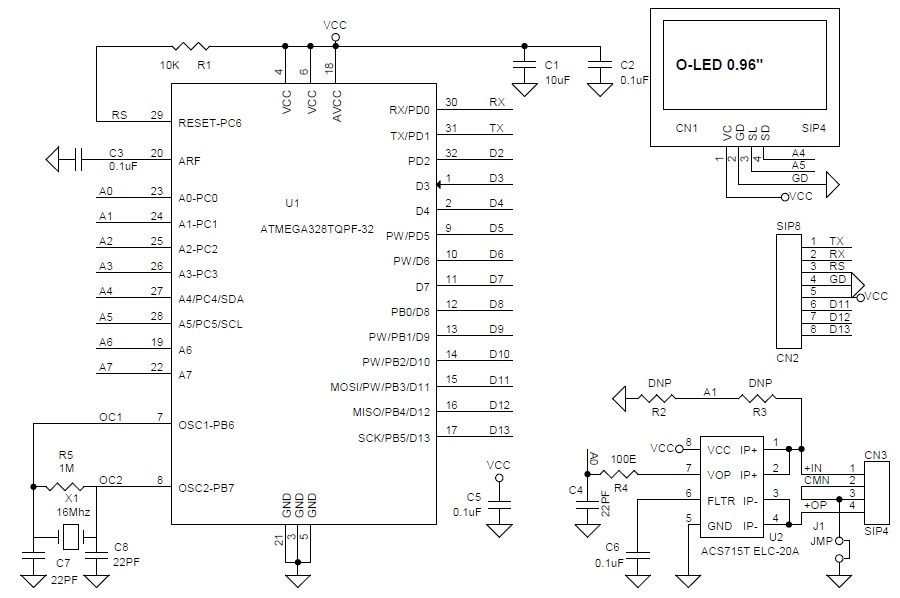
Schematic
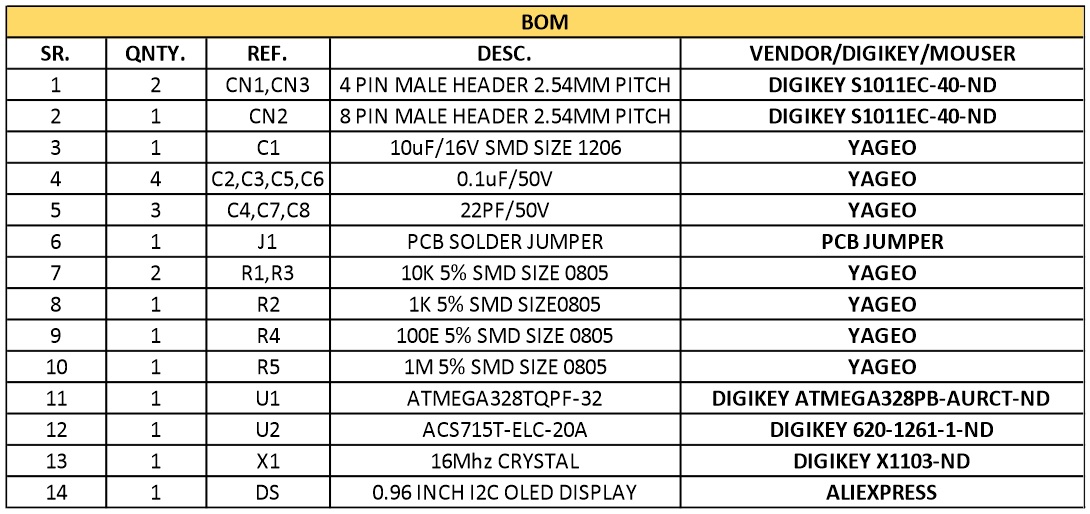
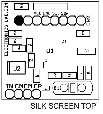
Parts List
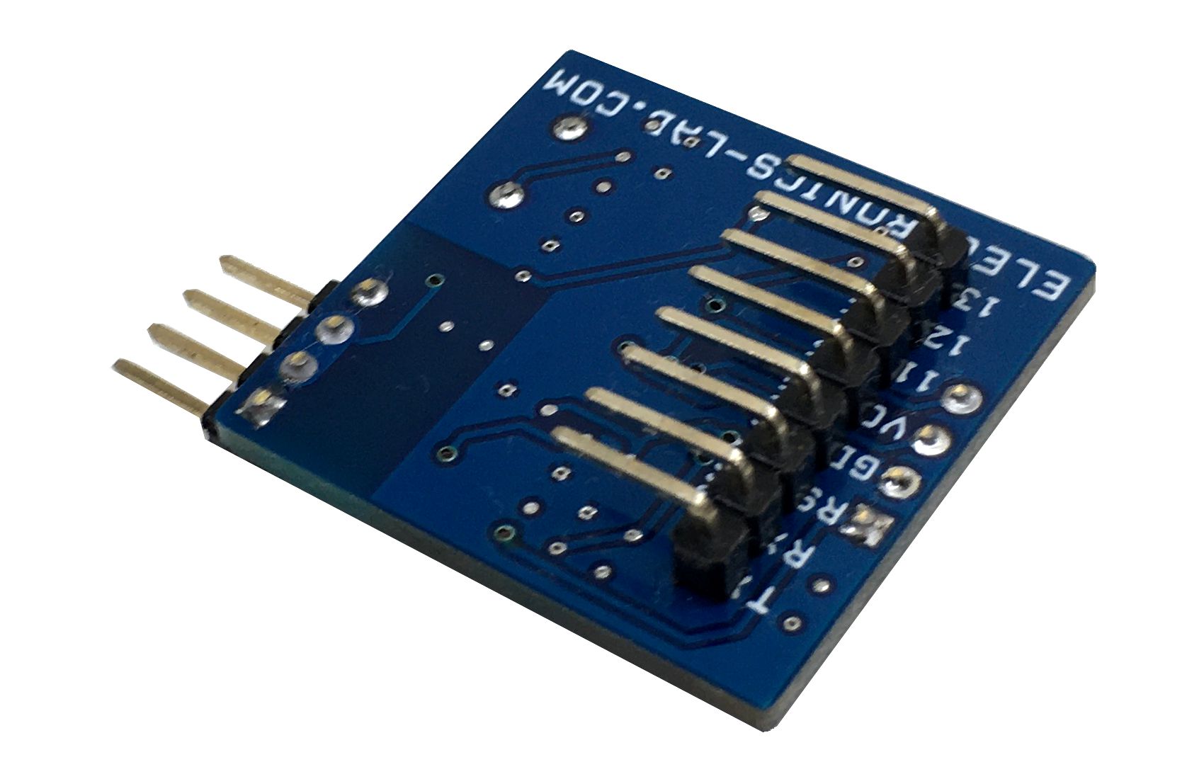
Arduino Programming Connections
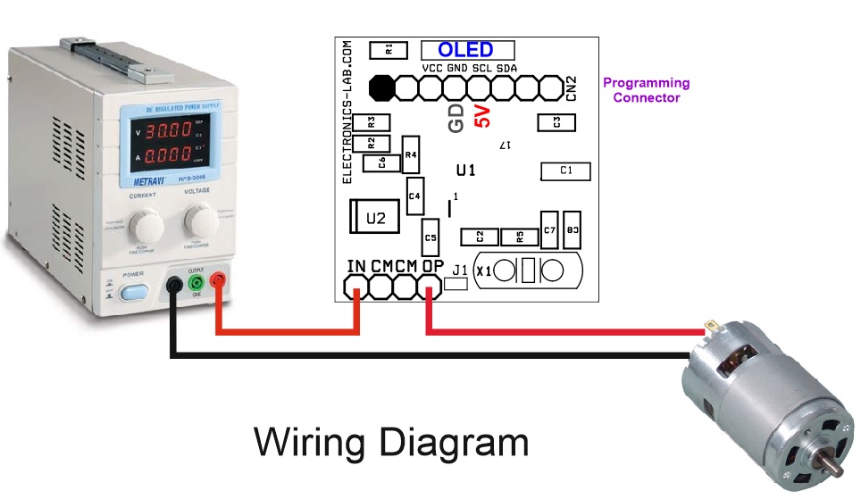
Test Connection
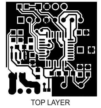
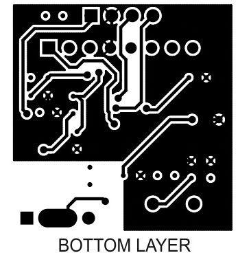
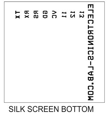
Gerber View
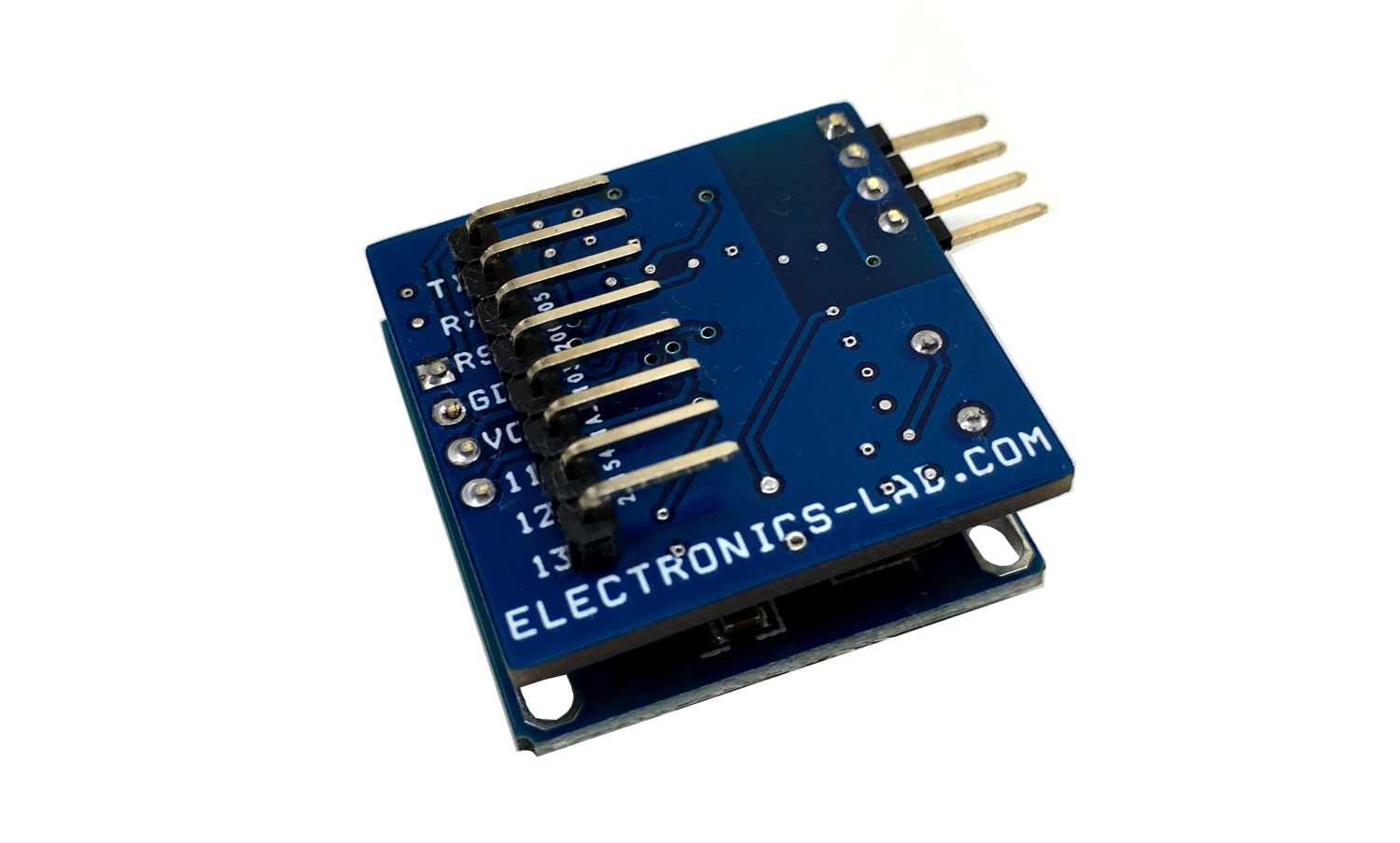
Photos
Video
ACS715 Datasheet
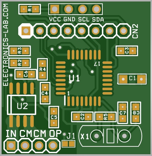
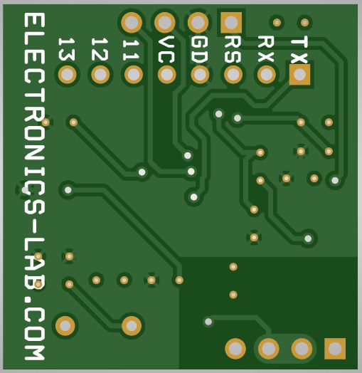
PCB
.png)