

Closed Loop Constant LED Light Source Using OPT101 Light Sensor and OPA569 Power OPAMP
- Rajkumar Sharma
- 25 Views
- moderate
- Tested
- SKU: EL130523
- Quote Now
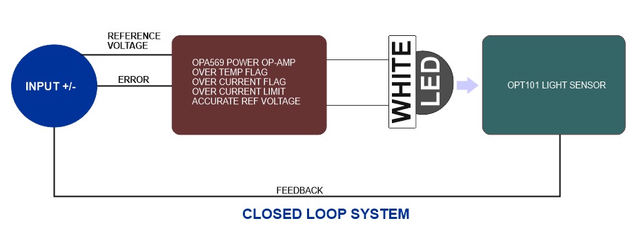
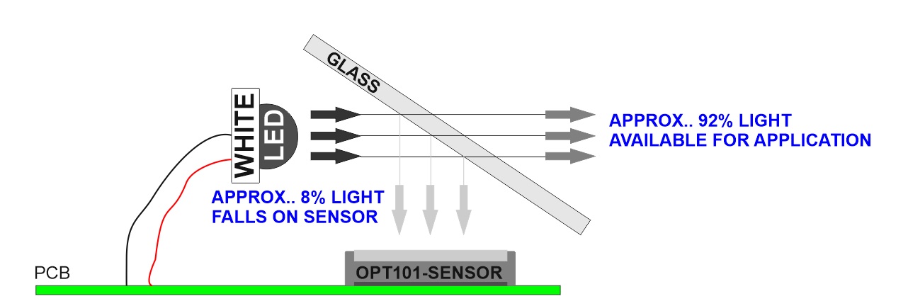
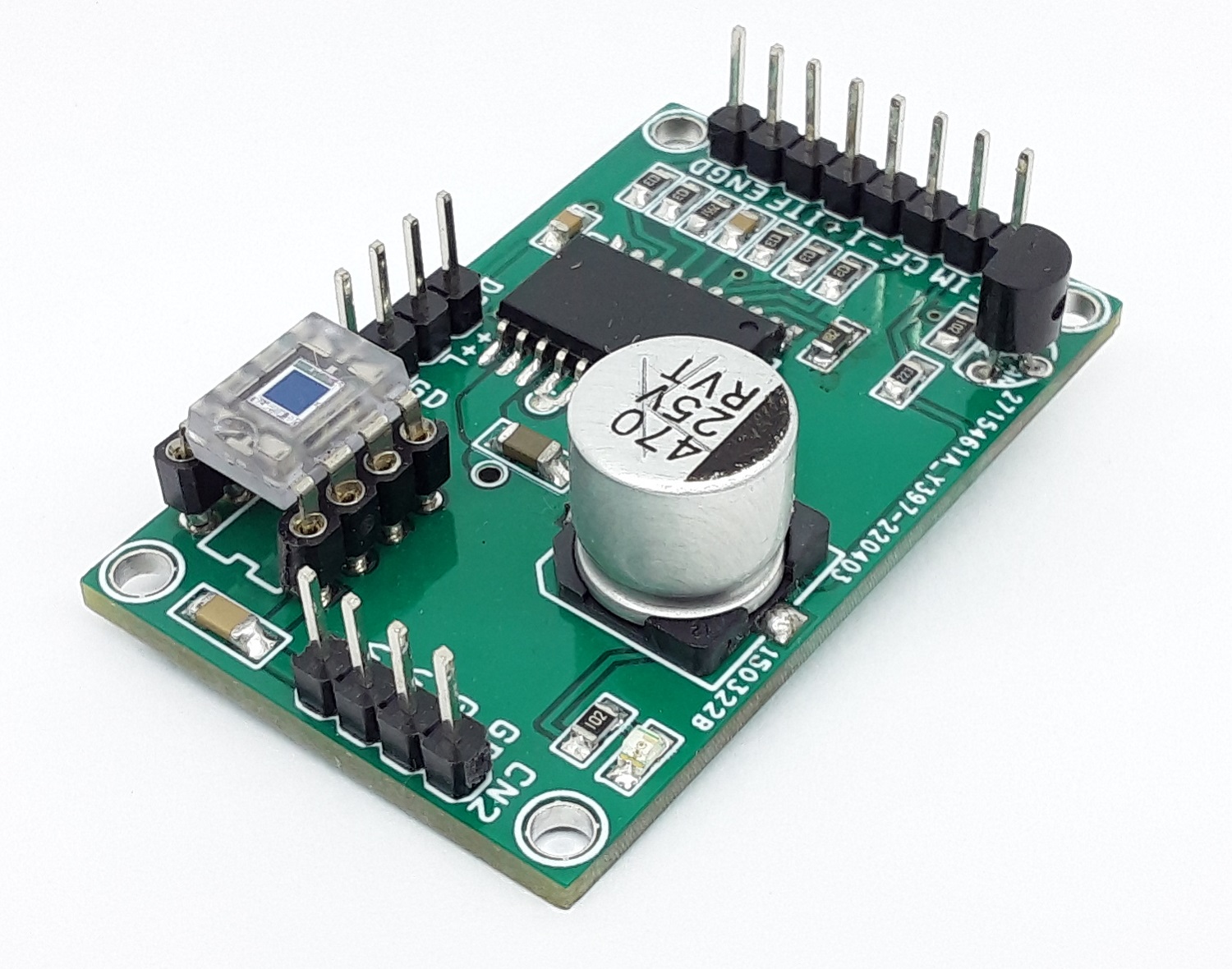
The project presented here is a precision closed-loop LED driver that provides very accurate constant light and can be used for photography, scientific research, and other applications that require an accurate light source. The project consists of light sensor OPT101 and OPA569 power OPAMP. OPT101 converts light into voltage, and OPA569 is used as an adjustable linear current source that controls the flow of current through the power LED. Installation of the Power LED and OPT101 Sensor is shown in the figure below. The overcurrent limit of LED is set to 1A using resistor R4. LM336 provides an accurate voltage reference to OPAMP which is 0.5V. The circuit works in a closed loop. At power ON, the LED light reflects to the sensor, and OPT101 provides the voltage output as the light level falls on the sensor, this voltage is fed to power op-amp, and op-amp compares the input voltage from OPT101 and reference voltage 0.5V. If there is an error, the op-amp controls the current of the LED to match the disparity between the output and input. This way light level is maintained and this is constant. It is important to have proper housing for the sensor so external/ambient light should not fall on the sensor, otherwise constant light will not be maintained.
Closed Loop Control
More Info about Constant Light Source
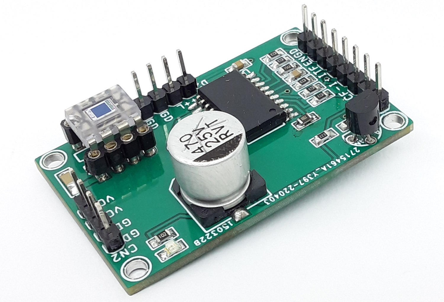
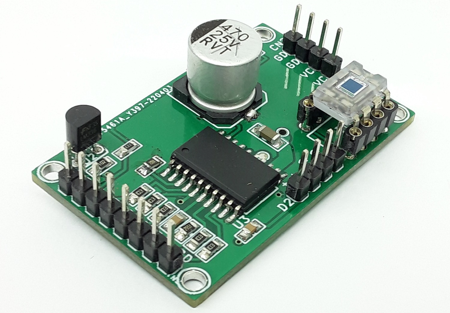
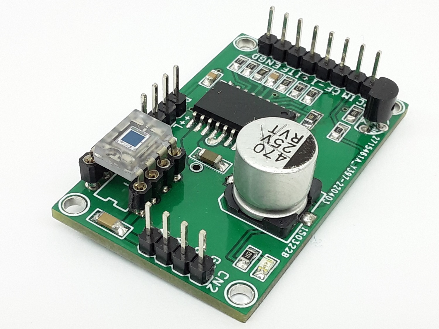
OPT101 sensor chip mounted horizontally on the PCB, 90-degree socket is available for easy mount
https://www.digikey.com/en/products/detail/aries-electronics/08-810-90/106399
What is a Closed Loop System?
- https://www.electronics-tutorials.ws/systems/closed-loop-system.html
- https://control.com/textbook/closed-loop-control/analog-electronic-pid-controllers/
Connections and other important details
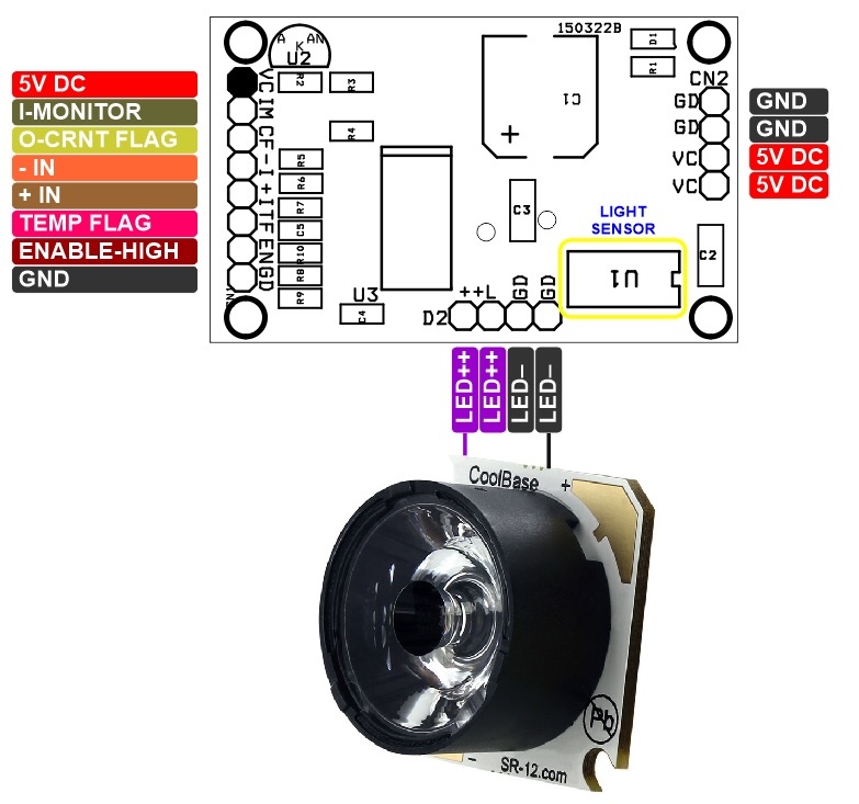
- CN1: Pin 1 = VCC 5V DC, Pin 2 = IMO Current Monitor Output, Pin 3 = Over Current Flag, Pin 4 = Op-Amp -IN, Pin5 = Op-Amp +IN, Pin 6 = Over Temp Flag, Pin 7 = Enable, Pin 8 GND
- Enable Pin 7 CN1 = High Enable, Low Disable the output
- CN1: Pin 2, Pin 3, Pin 4, Pin 5 Pin 6 are optional and can be used for microcontroller interface.
- D2: Power LED Pin 1 = +LED, Pin 2 = +LED, Pin 3 = -LED, Pin 4 = -LED
- CN2: Pin 1 = VCC +5V DC, Pin 2 = VCC +5V DC, Pin 3 = GND, Pin 4 = GND
Features
- Operating Power Supply 5V DC @ 1Amps
- Load (LED) up to 700mA
- Very Accurate LED Light Source
- Copper Area provided for heat management of OPA569
- Header Connector for LED and Power Input
- On Board Optional Power LED
- PCB Dimensions 46.83 x 29.53mm
- 4 x 2.5mm Mounting Holes
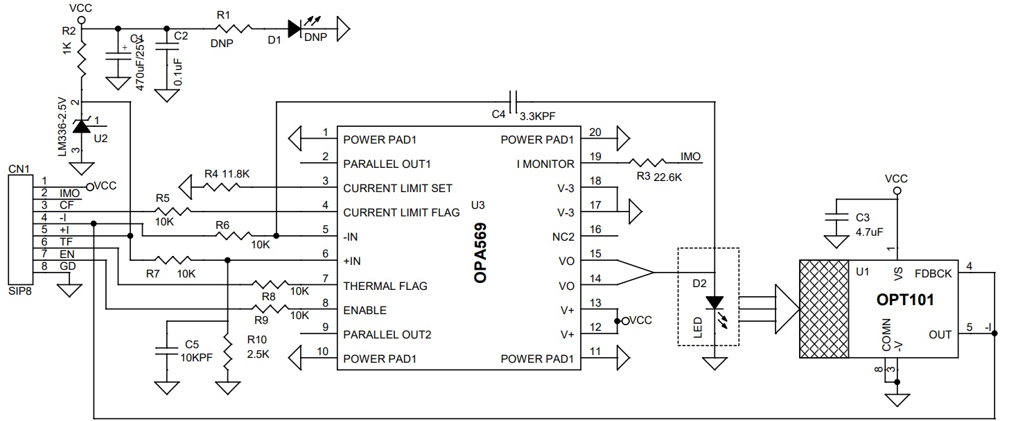
Schematic
Parts List
| NO. | QNTY. | REF. | DESC | MANUFACTURER | SUPPLIER | PART NO |
|---|---|---|---|---|---|---|
| 1 | 1 | CN1 | 8 PIN MALE HEADER PITCH 2.54MM | WURTH | DIGIKEY | 732-5321-ND |
| 2 | 1 | C1 | 470uF/25V OR 220uF/16V SMD ELECTROLYTIC | PANASONIC | DIGIKEY | PCE4605CT-ND |
| 3 | 1 | C2 | 0.1uF/50V CERAMIC SMD SIZE 0805 | YAGEO/MURATA | DIGIKEY | |
| 4 | 1 | C3 | 4.7uF/10V CERAMIC SMD SIZE 0805 | YAGEO/MURATA | DIGIKEY | |
| 5 | 1 | C4 | 3.3KPF/50V CERAMIC SMD SIZE 0805 | YAGEO/MURATA | DIGIKEY | |
| 6 | 1 | C5 | 10KPF/50V SMD SIZE 0805 | YAGEO/MURATA | DIGIKEY | |
| 7 | 2 | R1,D1 | DO NOT INSTALL | |||
| 8 | 1 | D2 | 4 PIN MALE HEADER PITCH 2.54MM FOR LED | WURTH | DIGIKEY | 732-5317-ND |
| 9 | 1 | R2 | 1K 1% SMD SIZE 0805 | YAGEO/MURATA | DIGIKEY | |
| 10 | 1 | R3 | 22.6K 1% SMD SIZE 0805 | YAGEO/MURATA | DIGIKEY | |
| 11 | 1 | R4 | 11.8K 1% SMD SIZE 0805 | YAGEO/MURATA | DIGIKEY | |
| 12 | 5 | R5,R6,R7,R8,R9 | 10K 1% SMD SIZE 0805 | YAGEO/MURATA | DIGIKEY | |
| 13 | 1 | R10 | 2.5K 1% SMD SIZE 0805 | YAGEO/MURATA | DIGIKEY | |
| 14 | 1 | U1 | OPT101 DIP8 | TI | DIGIKEY | 296-23090-5-ND |
| 15 | 1 | U2 | LM336-2.5V TO92 | ON SEMI | DIGIKEY | 2156-LM336Z25-ND |
| 16 | 1 | U3 | OPA569 SO SMD | TI | DIGIKEY | 296-26292-1-ND |
| 17 | 1 | CN2 | 4 PIN MALE HEADER PITCH 2.54MM | WURTH | DIGIKEY | 732-5317-ND |
Connections
System Diagram
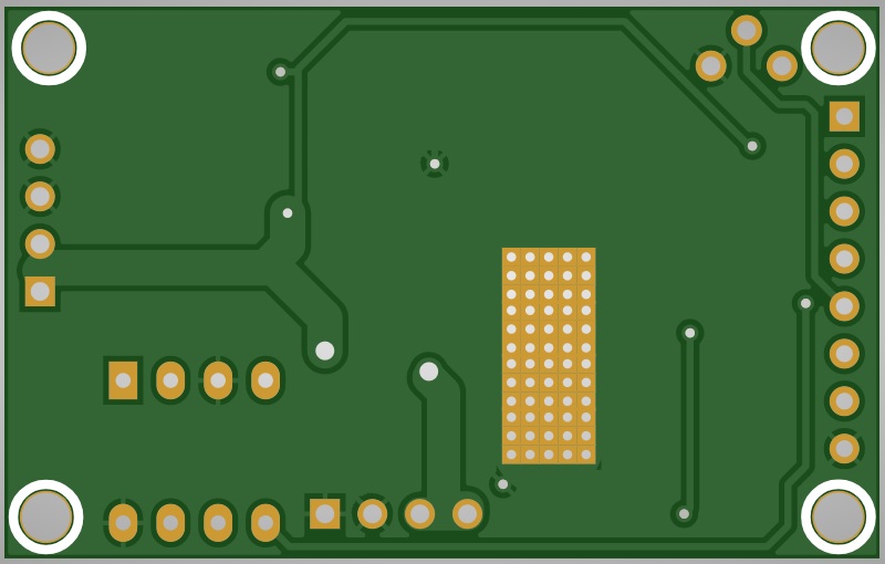
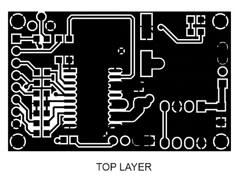
Gerber View
Photos


Video
OPA569 Datasheet


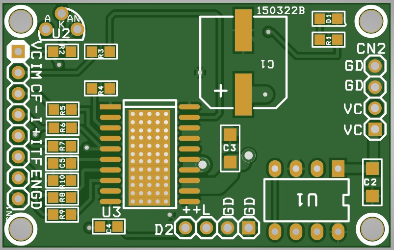
PCB


.png)