

7-segment Mini Clock using PIC16F628A and DS1307 RTC
- Michail Papadimitriou
- mixos@otenet.gr
- 10.338 Views
- easy
- Tested
- SKU: EL93773
- Quote Now
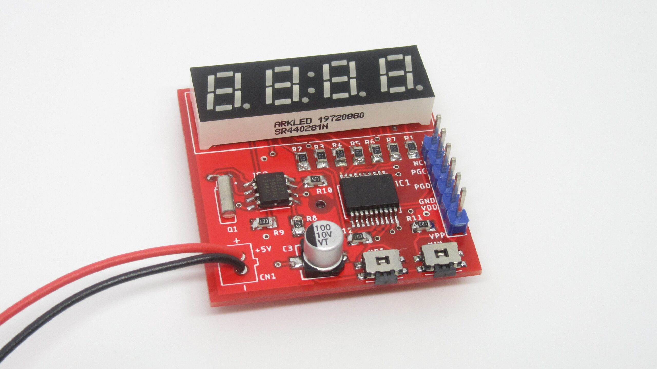
This is a minimal and small clock based on PIC16F628A microcontroller and DS1307 RTC IC. It is able to only show the time on a small 7-segment display with a total of 4 segments. The display we used is a 0.28″ SR440281N RED common cathode display bought from LCSC.com, but you can use other displays as well such as the 0.56″ Kingbright CC56-21SRWA. This project is heavily inspired by the “Simple Digital Clock with PIC16F628A and DS1307” in the case of schematic and we also used the same .hex as”Christo”.
Schematic
The schematic is straight forward. The heart is the PIC16F628A microcontroller running on the internal 4MHz oscillator, so no external crystal is needed. This saves us 2 additional IOs. The RESET Pin (MCLR) is also used as input for one of the buttons. All display segments are connected to PORTB and COMs are connected to PORTA. The RTC chip is also connected to PORTA using the I2C bus.
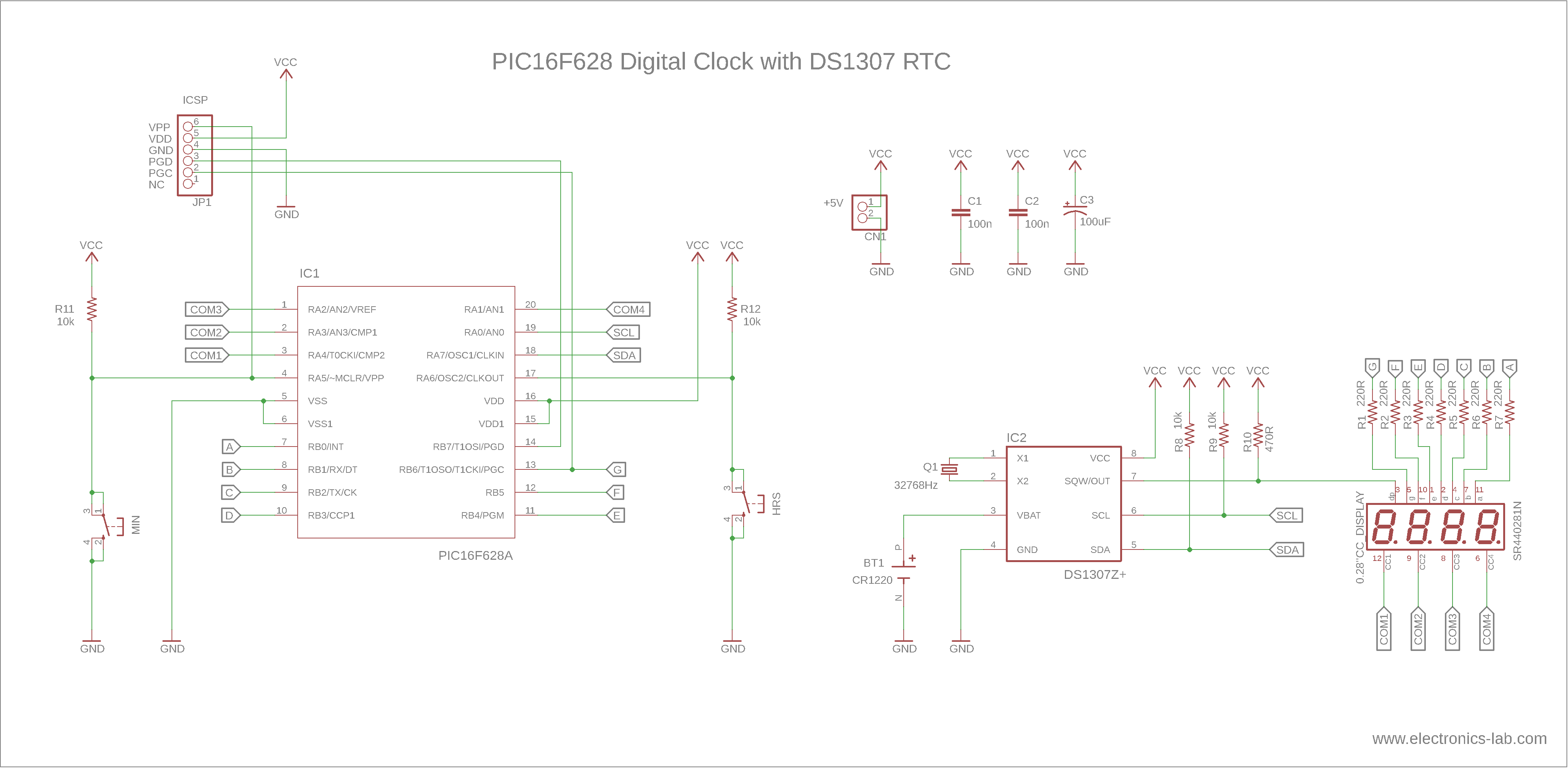
The refresh rate of the digits is about 53Hz and there is no visible flickering. The display segments are time-multiplexed and this makes them appear dimmer than the specifications. To compensate we are going to use some low resistors on the anodes. “Christo” tested it with different values for current limiting resistors R1-R7 and below 220Ω the microcontroller starts to misbehave (some of the digits start to flicker) above 220 Ohm everything seems OK. On the display we used the two middle dots are not connected to any pin on the package, so for the seconds’ indicators, we used the “comma” dots. These pins are connected to the SQW pin of the DS1307, which provides a square wave output with 1 sec period. The SQW pin is open drain, so we need to add a pull-up resistor. Τhe value of this resistor is chosen at 470Ω, after some trial and error testing. On the input side of the MCU, there are two buttons for adjusting the MINUTES and HOURS of the clock as indicated on the schematic. Onboard there is also an ICSP Programming connector, to help with the firmware upload. Finally, there is one unused pin left (RB7), which can be used for additional functionality, like adding a buzzer or an additional LED.
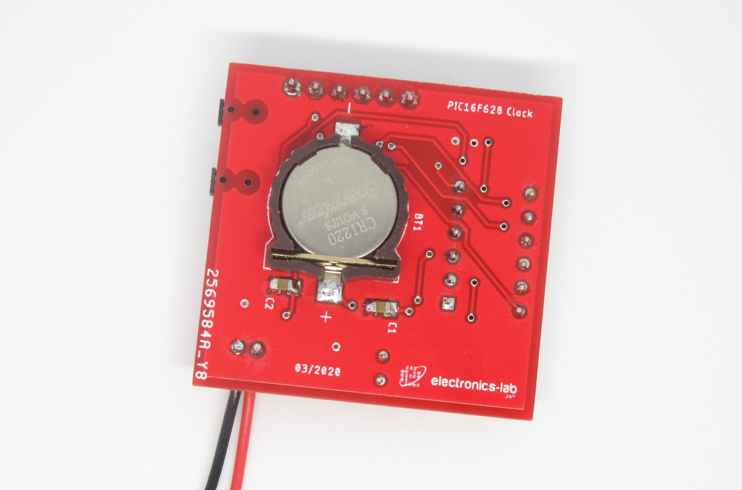
The DS1307 RTC needs an external crystal to keep the internal clock running and a backup battery to keep it running while the main power is OFF. So, the next time you power ON the clock the time would be current. To keep the overall board dimensions small we used a CR1220 battery holder with the appropriate 3V battery. Power consumption is about 35-40mA @ 5V input.
Code
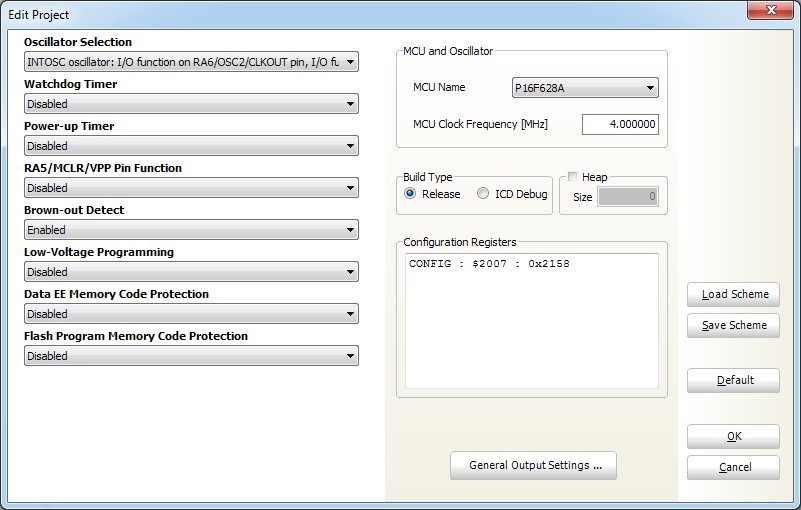
According to the author, the code is written and compiled with MikroC Pro and uses the build-in software I2C library for communicating with RTC chip. If you want to use MPLAB IDE for compiling the code you should write your own I2C library from scratch. For programming the board we used PICkit 3 programmer and software. In this case, in the “Tools” menu check the option “Use VPP First Program Entry“.
The code for this project is listed below. Additionally, you will need the “Digital Clock (PIC16F628A, DS1307, v2).h” file which can be found on the .zip in downloads below. Compiled .hex file is also provided on the same .zip file.
#include "Digital Clock (PIC16F628A, DS1307, v2).h"
#define b1 RA6_bit
#define b2 RA5_bit

// b1_old, b2_old - old state of button pins
// hour10, hour1 - tens and ones of the hour
// min10, min1 = tens and ones of the minutes
byte b1_old, b2_old, hour1, hour10, min1, min10;

// definitions for Software_I2C library
sbit Soft_I2C_Scl           at RA0_bit;
sbit Soft_I2C_Sda           at RA7_bit;
sbit Soft_I2C_Scl_Direction at TRISA0_bit;
sbit Soft_I2C_Sda_Direction at TRISA7_bit;


//  correct bits for each digit
//     RB6 RB5 RB4 RB3 RB2 RB1 RB0
//     g   f   e   d   c   b   a
//  0: 0   1   1   1   1   1   1   0x3F
//  1: 0   0   0   0   1   1   0   0x06
//  2: 1   0   1   1   0   1   1   0x5B
//  3: 1   0   0   1   1   1   1   0x4F
//  4: 1   1   0   0   1   1   0   0x66
//  5: 1   1   0   1   1   0   1   0x6D
//  6: 1   1   1   1   1   0   1   0x7D
//  7: 0   0   0   0   1   1   1   0x07
//  8: 1   1   1   1   1   1   1   0x7F
//  9: 1   1   0   1   1   1   1   0x6F
// BL: 0   0   0   0   0   0   0   0x00

const byte segments[11] = {0x3F, 0x06, 0x5B, 0x4F, 0x66, 0x6D, 0x7D, 0x07, 0x7F, 0x6F, 0x00};


//***********************************************//
//   Sets read or write mode at select address   //
//***********************************************//
void DS1307_Select(byte Read, byte address) {
     Soft_I2C_Start();
     Soft_I2C_Write(0xD0);       // start write mode
     Soft_I2C_Write(address);    // write the initial address
     if (Read) {
        Soft_I2C_Stop();
        Soft_I2C_Start();
        Soft_I2C_Write(0xD1);    // start read mode
     }
}

//********************************//
//   Initialize the DS1307 chip   //
//********************************//
void DS1307_Init() {
     byte sec, m, h;
     DS1307_Select(1, 0);                 // start reading at address 0
     sec = Soft_I2C_Read(1);              // read seconds byte
     m = Soft_I2C_Read(1);                // read minute byte
     h = Soft_I2C_Read(0);                // read hour byte
     Soft_I2C_Stop();
     if (sec > 127) {                     // if the clock is not running  (bit 7 == 1)
        DS1307_Select(0, 0);              // start writing at address 0
        Soft_I2C_Write(0);                // start the clock (bit 7 = 0)
        Soft_I2C_Stop();
        DS1307_Select(0, 7);              // start writing at address 7
        Soft_I2C_Write(0b00010000);       // enable square wave output 1 Hz
        Soft_I2C_Stop();
     }
     m = (m >> 4)*10 + (m & 0b00001111);  // converting from BCD format to decimal
     if (m > 59) {
        DS1307_Select(0, 1);              // start writing at address 1
        Soft_I2C_Write(0);                // reset the minutes to 0
        Soft_I2C_Stop();
     }
     if (h & 0b01000000) {                // if 12h mode (bit 6 == 1)
        if (h & 0b00100000)               // if PM (bit 5 == 1)
           h = 12 + ((h >> 4) & 1)*10 + (h & 0b00001111);
        else
           h = ((h >> 4) & 1)*10 + (h & 0b00001111);
     }
     else
        h = ((h >> 4) & 3)*10 + (h & 0b00001111);
     if (h > 23) {
        DS1307_Select(0, 2);              // start writing at address 2
        Soft_I2C_Write(0);                // reset the hours to 0 in 24h mode
        Soft_I2C_Stop();
     }
}


void incrementH() {     // increments hours and write it to DS1307
     hour1++;
     if ((hour10 < 2 && hour1 > 9) || (hour10 == 2 && hour1 > 3)) {
        hour1 = 0;
        hour10++;
        if (hour10 > 2)
           hour10 = 0;
     }
     DS1307_Select(0, 2);
     Soft_I2C_Write((hour10 << 4) + hour1);
     Soft_I2C_Stop();
}


void incrementM() {     // increments minutes and write it to DS1307
     min1++;
     if (min1 > 9) {
        min1 = 0;
        min10++;
        if (min10 > 5)
           min10 = 0;
     }
     DS1307_Select(0, 0);
     Soft_I2C_Write(0);                       // reset seconds to 0
     Soft_I2C_Write((min10 << 4) + min1);     // write minutes
     Soft_I2C_Stop();
}

void main(){
     // pos: current digit position;
     // counter1, counter2: used as flag and for repeat functionality for the buttons
     // COM[]: drive the common pins for the LED display
     byte pos, counter1, counter2, COM[4] = {0b11101111, 0b11110111, 0b11111011, 0b11111101};
     CMCON = 0b00000111;             // comparator off
     TRISA = 0b01100000;
     TRISB = 0b00000000;
     b1_old = 1;
     b2_old = 1;
     counter1 = 0;
     counter2 = 0;
     pos = 0;
     Soft_I2C_Init();
     DS1307_Init();
     while (1) {
           DS1307_Select(1, 1);      // select reading at address 1
           min1 = Soft_I2C_Read(1);  // read minutes byte
           hour1 = Soft_I2C_Read(0); // read houts byte
           Soft_I2C_Stop();
           min10 = min1 >> 4;
           min1 = min1 & 0b00001111;
           hour10 = hour1 >> 4;
           hour1 = hour1 & 0b00001111;
           if (b1 != b1_old) {        // if the button1 is pressed or released
              b1_old = b1;
              counter1 = 0;
           }
           if (!b1_old) {             // if the button1 is pressed
              if (counter1 == 0)
                 incrementH();        // increment hour
              counter1++;
              if (counter1 > 50)      // this is repeat functionality for the button1
                 counter1 = 0;
           }
           if (b2 != b2_old) {        // if the button2 is pressed or released
              b2_old = b2;
              counter2 = 0;
           }
           if (!b2_old) {             // if the button2 is pressed
              if (counter2 == 0)
                 incrementM();        // increment minutes and reset the seconds to 0
              counter2++;
              if (counter2 > 50)      // this is repeat functionality for the button2
                 counter2 = 0;
           }

           TRISA = TRISA | 0b00011110;       // set all 4 pins as inputs
           switch (pos) {                    // set proper segments high
             case 0: PORTB = segments[hour10]; break;
             case 1: PORTB = segments[hour1]; break;
             case 2: PORTB = segments[min10]; break;
             case 3: PORTB = segments[min1]; break;
           }
           TRISA = TRISA & COM[pos];         // set pin at current position as output
           PORTA = PORTA & COM[pos];         // set pin at current position low
           pos++;                            // move to next position
           if (pos > 3) pos = 0;
     }
}
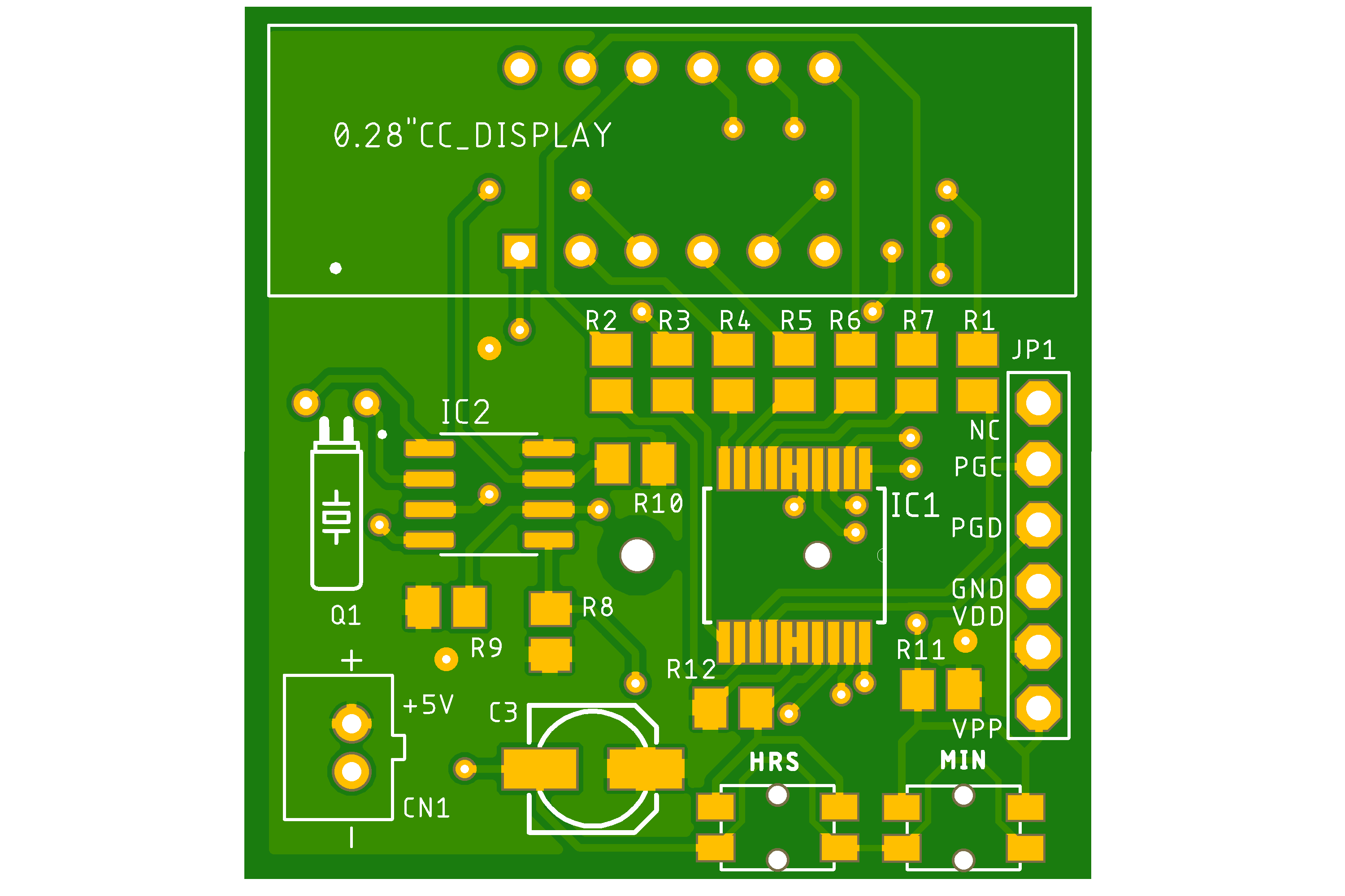
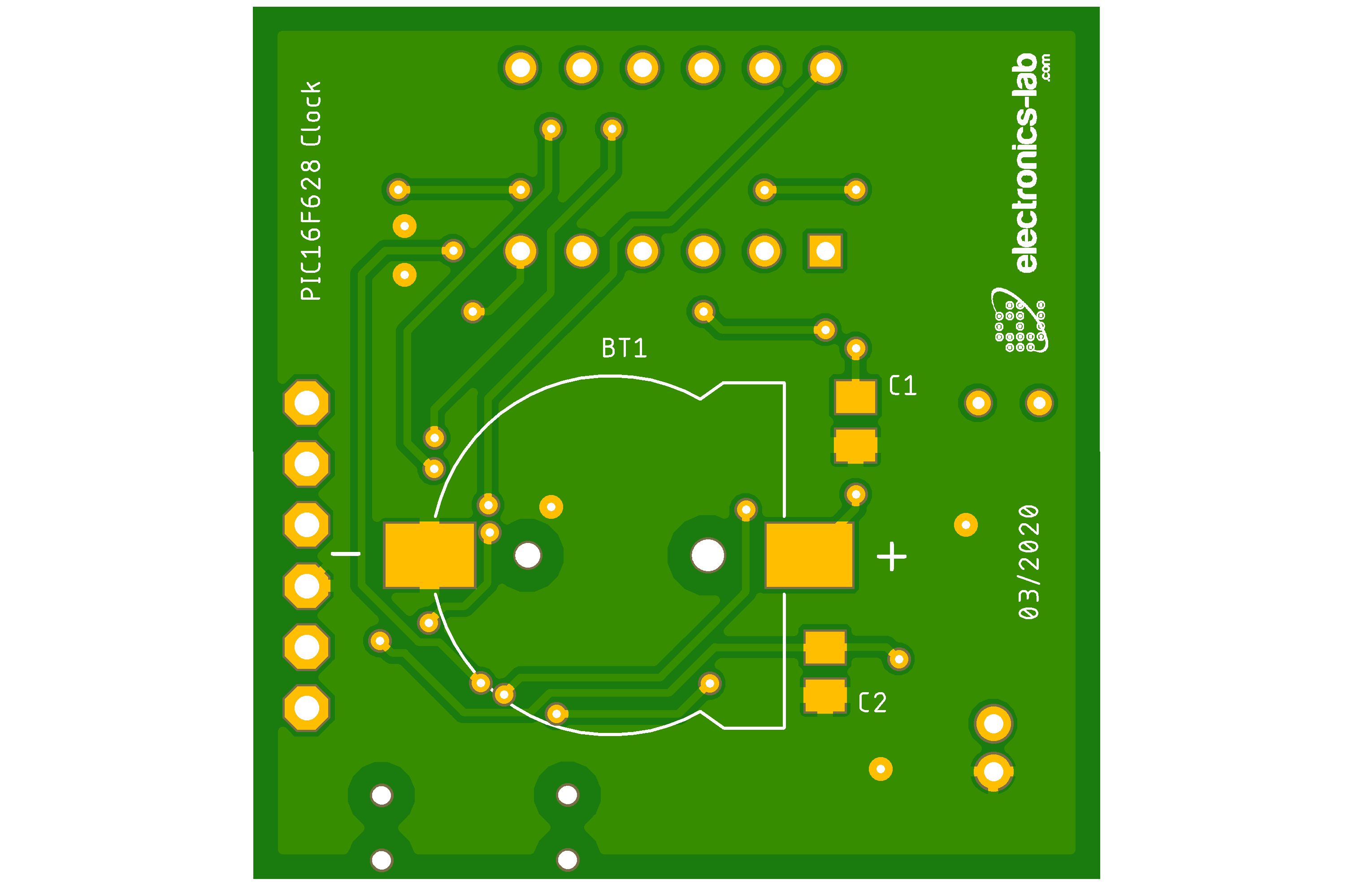
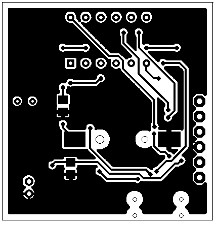
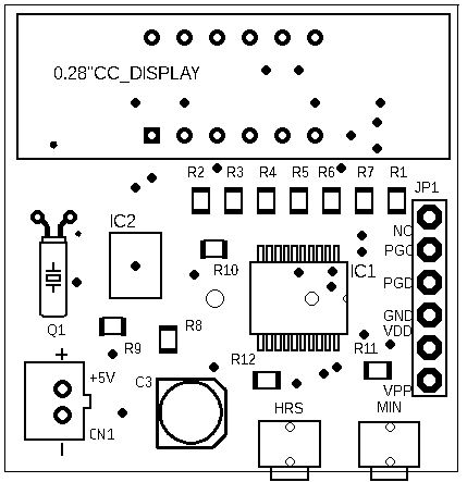
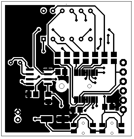
PCB
PCB is designed with Autodesk EAGLE and design files are available in downloads below. The overall dimensions of the board are 35.56 x 36.61 mm and we used almost SMD components.
Autodesk EAGLE file Viewer
Parts List
| Part | Value | Size |
|---|---|---|
| R1 to R7 | 220Ω | 0805 |
| R8-R9 | 10k | 0805 |
| R10 | 470Ω | 0805 |
| R11-R12 | 10k | 0805 |
| C1-C2 | 100nF | 0805 |
| C3 | 100uF/16V | SMD |
| Q1 | 32768Hz Crystal | TH |
| IC1 | PIC16F628A-I/SS | SSOP20 |
| IC2 | DS1307Z+ | SO8 |
| LED Display | SR440281N | 0.28" |
| BT1 | CR1220 BAT holder | BS-1220-2 |
| JP1 | PIN Header | 6 PINs |
| CN1 | JST PH Connector | 2 PINs |
| Buttons | PTCF-V-T/R | 4.7*4.5*1.67 |
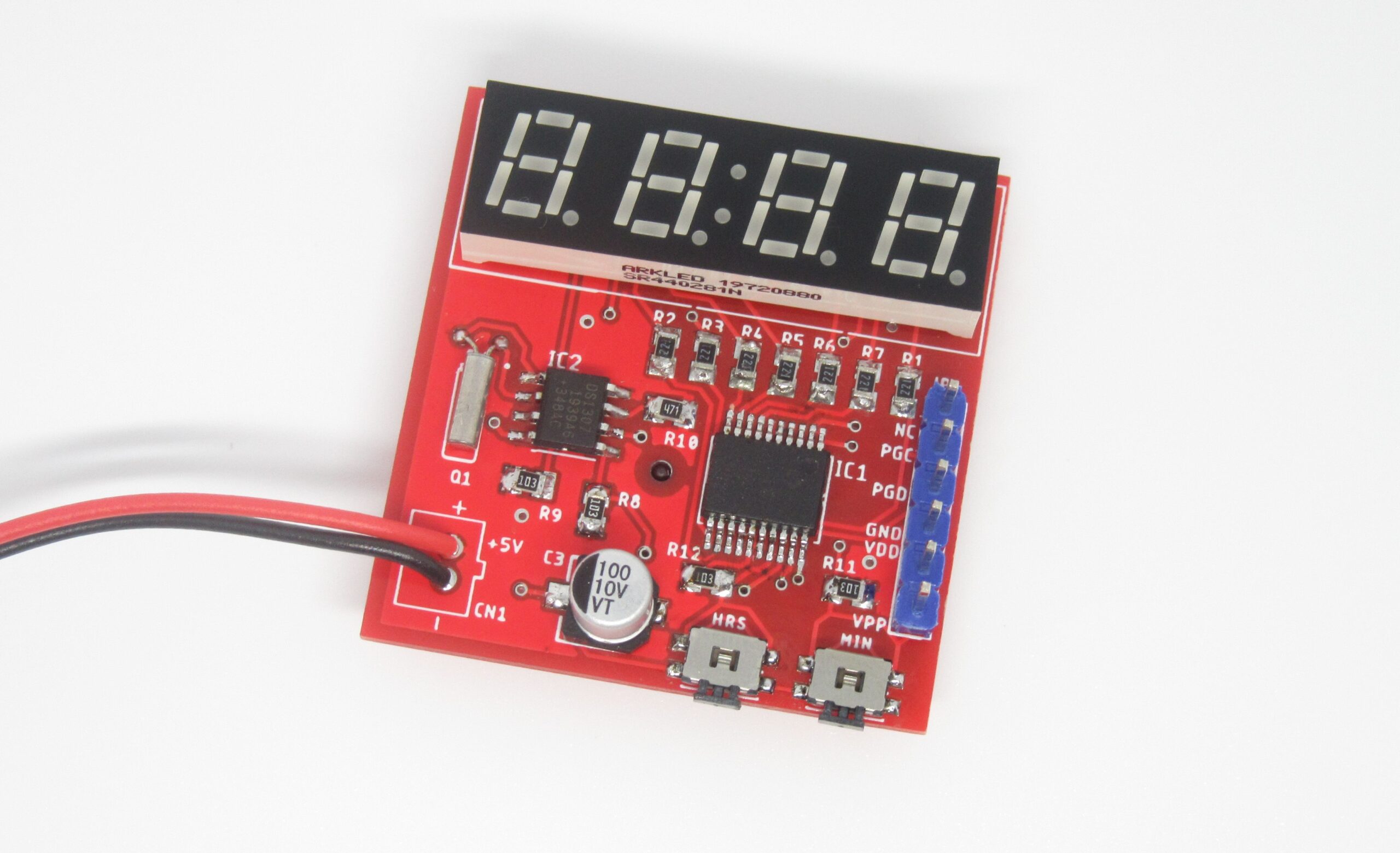
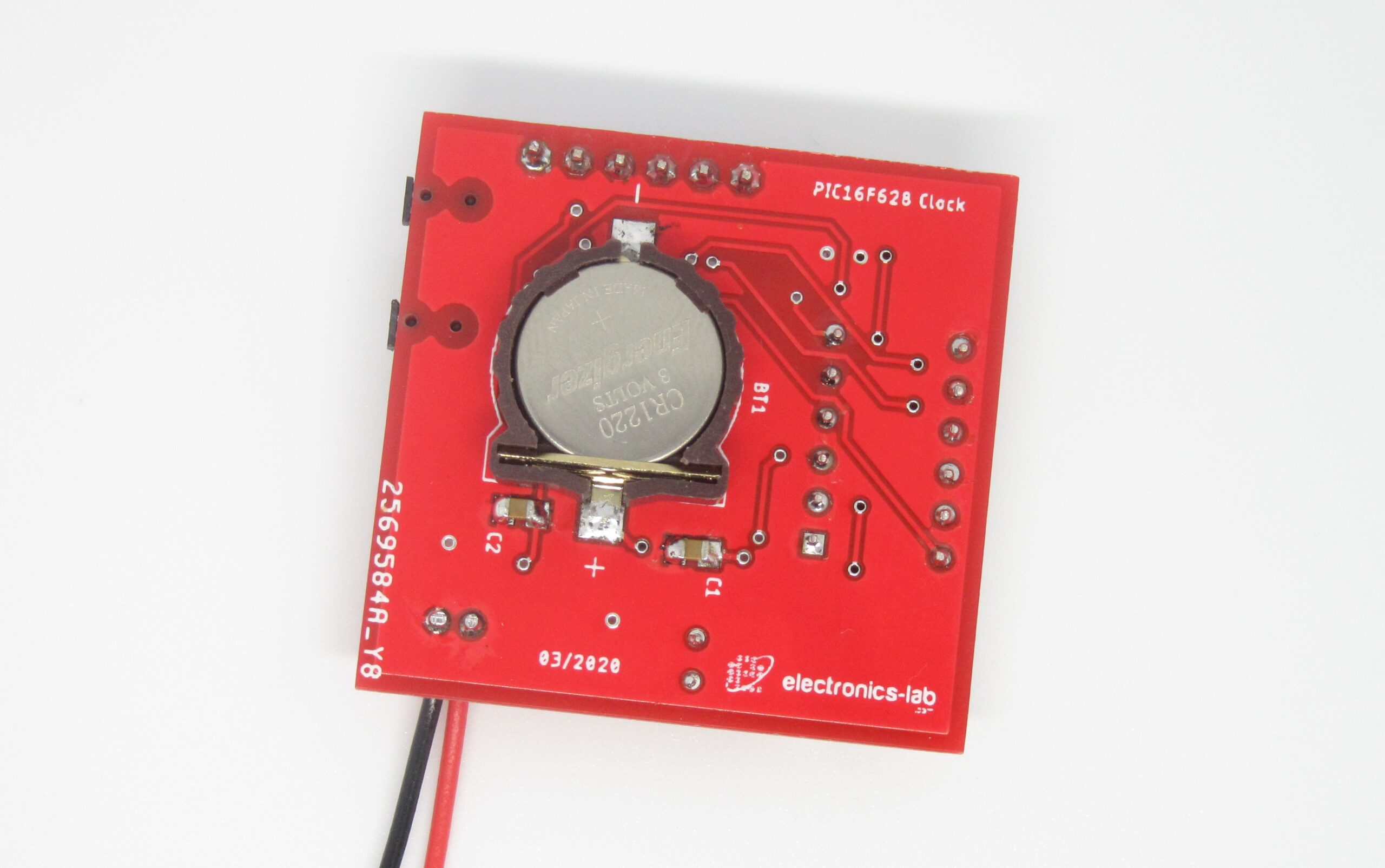
Photos
Video
PIC16F628A Datasheet
DS1307 Datasheet


PCB
.png)


")
what modification to do 12hr format and if can indicate am/pm
What if we need to use big displays?
Sorry, 12h format is not supported by this firmware. You will have to code this function.
how can use coomon anode display with sch and code modifications ? can you explain pls..