

Strain Gauge Sensor Amplifier or Single Supply Instrumentation Amplifier
- Rajkumar Sharma
- 4.343 Views
- easy
- Tested
- SKU: EL101160
- Quote Now
This is a new project, a single supply instrumentation amplifier with onboard bridge configuration, and a 2.5V precision reference voltage chip. The project can be configured for applications such as thermocouple amplifier, bridge amplifier, ECG amplifier, pressure sensors, medical instrumentation, portable instrumentation, RTD sensor amplifier. The project is based on INA333 micropower, zero drift, rail to rail out instrumentation amplifier chip. REF5025AID chip provides a precise 2.5V reference voltage. The board can be configured as an instrumentation amplifier or as a strain gauge amplifier with few easy changes.
Strain Gauge Amplifier
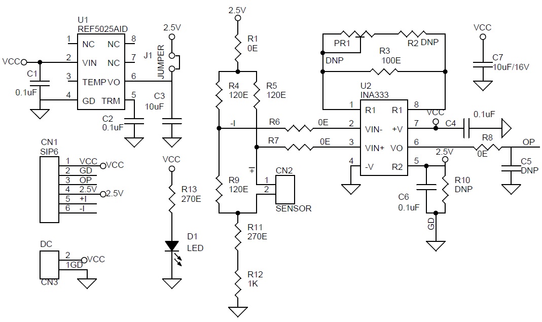
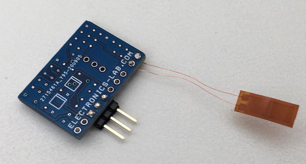
The circuit shown here is a simple example of a Strain Gauge Amplifier in a bridge configuration, this strain gauge circuit accurately measures the resistance of a strain gauge sensor placed in a bridge configuration. The resistance of the strain gauge sensor varies with applied force, change in resistance is directly proportional to how much strain the sensor is experiencing due to the force applied. Changes in the strain gauge resistance create a differential voltage that is amplified by an instrumentation amplifier INA333. The amplifiers have very high input impedance and therefore introduce negligible error with respect to the bridge resistance. The output voltage of the instrumentation amplifier will be depending on the sensor’s value and variation in resistance value. The bridge excitation voltage and instrumentation amplifier reference voltage 2.5V are supplied using the REF5025. A reference voltage at mid-supply (5V DC) biases the output voltage of the instrumentation amplifier to allow differential measurements in the positive and negative direction. The common mode resistors, R1, R11 and R12, have two main functions; limit the current through the bridge and set the common mode of the instrumentation amplifier. I have used 120 Ohms Strain Gauge sensor and thus I have chosen bridge resistors R4, R5, and R9 also 120 Ohms to match the sensors impedance. Matching the bridge resistors with the strain gauge resistance produces a 0 V differential bridge voltage when the strain gauge resistance is at its nominal value. It is advisable to use very low tolerance resistors to minimize the offset and gain error due to the bridge resistors. Operating power supply 5V DC, D1 power LED, J1 PCB jumper closed. CN2 sensor connection, CN1 supply input, and sensor output, R3 100 Ohms resistor set the gain of Amplifier to approx. 1001.
Features
- Power Supply 5V DC
- Output 230mV to 4.7V DC
- Strain Gauge Nominal Resistance 120 Ohms
- Stain Gauge Resistance Variation 115 Ohms to 125 Ohms
- Sensor Gauge Factor 5%
- Bridge Excitation Voltage and Reference Voltage 2.5V DC
- PCB Dimensions 26.99 x 19.21 mm
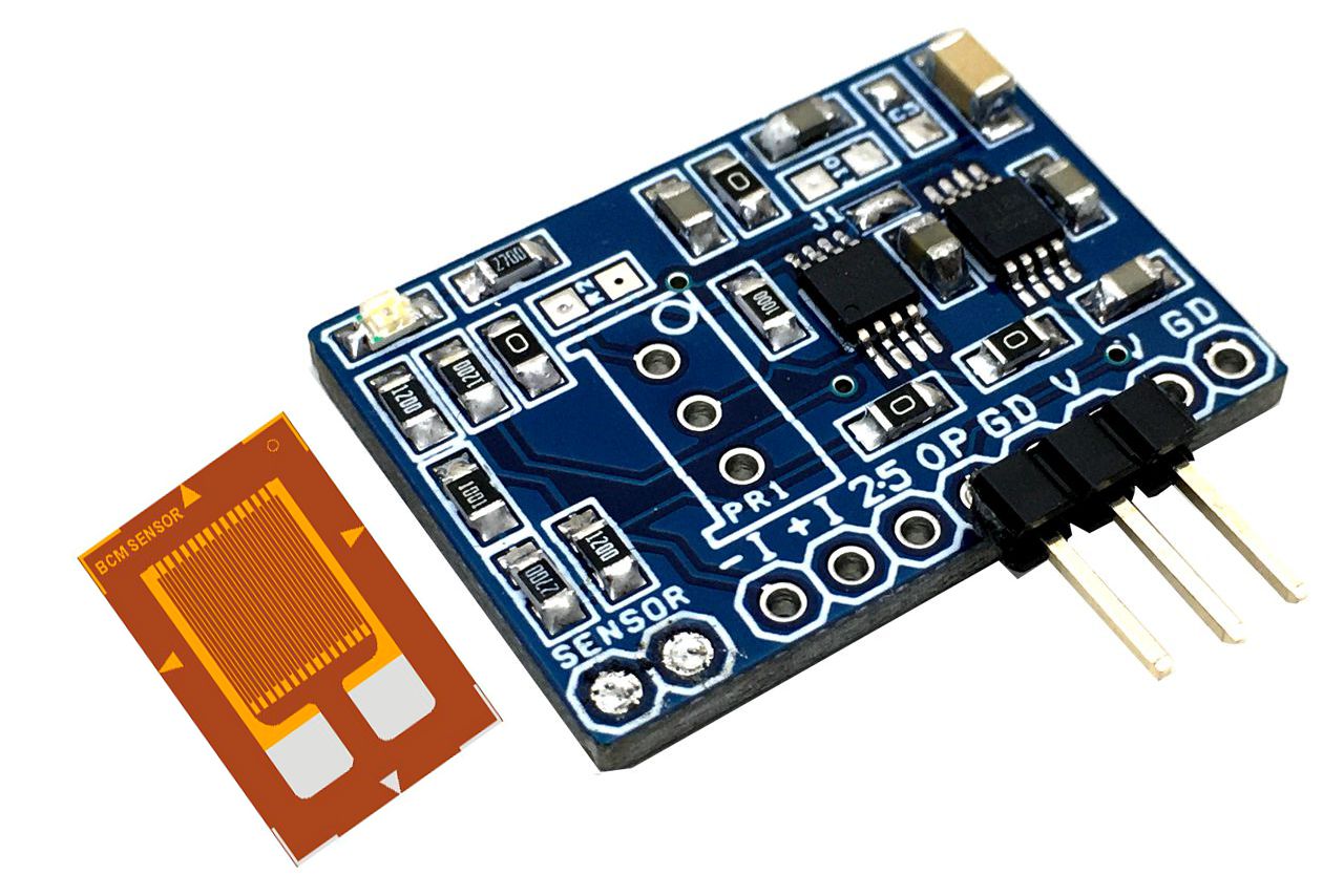
Strain Gauge Sensor
- Digi-Key Part Number: MMF002504-ND
- Manufacturer: Micro-Measurements (Division of Vishay Precision Group)
- Manufacturer Part Number: MMF002504
- Description: EA-06-250BG-120/LE STRAIN GAGES
- Detailed Description: Linear Strain Gauge ±5% 0.250″ (6.35mm) 0.125″ (3.18mm)
- Pattern Type: Linear
- Strain Range: ±5%
- Resistance: 120 Ohms
- Resistance Tolerance: ±0.15%
What is a Strain Gauge Sensor?
A strain gauge is a sensor whose resistance varies with applied force. The change in resistance is directly proportional to how much strain the sensor is experiencing due to the force applied. Strain Gauge sensors are available in different types, configuration and different dimensions and resistance.
Resistance of Sensor
The electric resistance between the two metal leads, solder tabs or cable ends for connecting the measuring cable is called the resistance of a strain gauge. Strain gauges are available with 120-ohm, 350-ohm, 700-ohm 1,000 ohm or 3000-ohm resistance.
Gauge Factor of Sensor
The gauge factor k of a strain gauge is the proportionality factor between the relative change in resistance DR/R0 and the strain to be measured e: DR/R0 = k · e the gauge factor, a dimensionless number, is sometimes also called the k factor. This gauge factor is determined for each production batch by measuring and is specified on each strain gauge package as a nominal value complete with tolerance. The gauge factors vary between production batches by just a few thousandths.
More Info on Gauge Sensor: https://www.omega.com/en-us/resources/strain-microstrain
The Board as Instrumentation Amplifier
The project also can be configured as a differential instrumentation amplifier for various applications. All-important pins of INA333 are easily accessible using header connectors to other devices or sensors. Omit R1, R4, R5, R9, R11, R12, Choose R3 or R2, and PR1 to adjust the gain of the amplifier, Choose R6, R7, 0ohms resistors, and differential pins +I and -I are available as input. Open the J1 jumper if the reference voltage is not required.
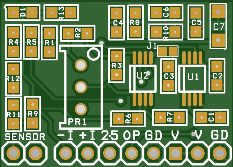
Schematic
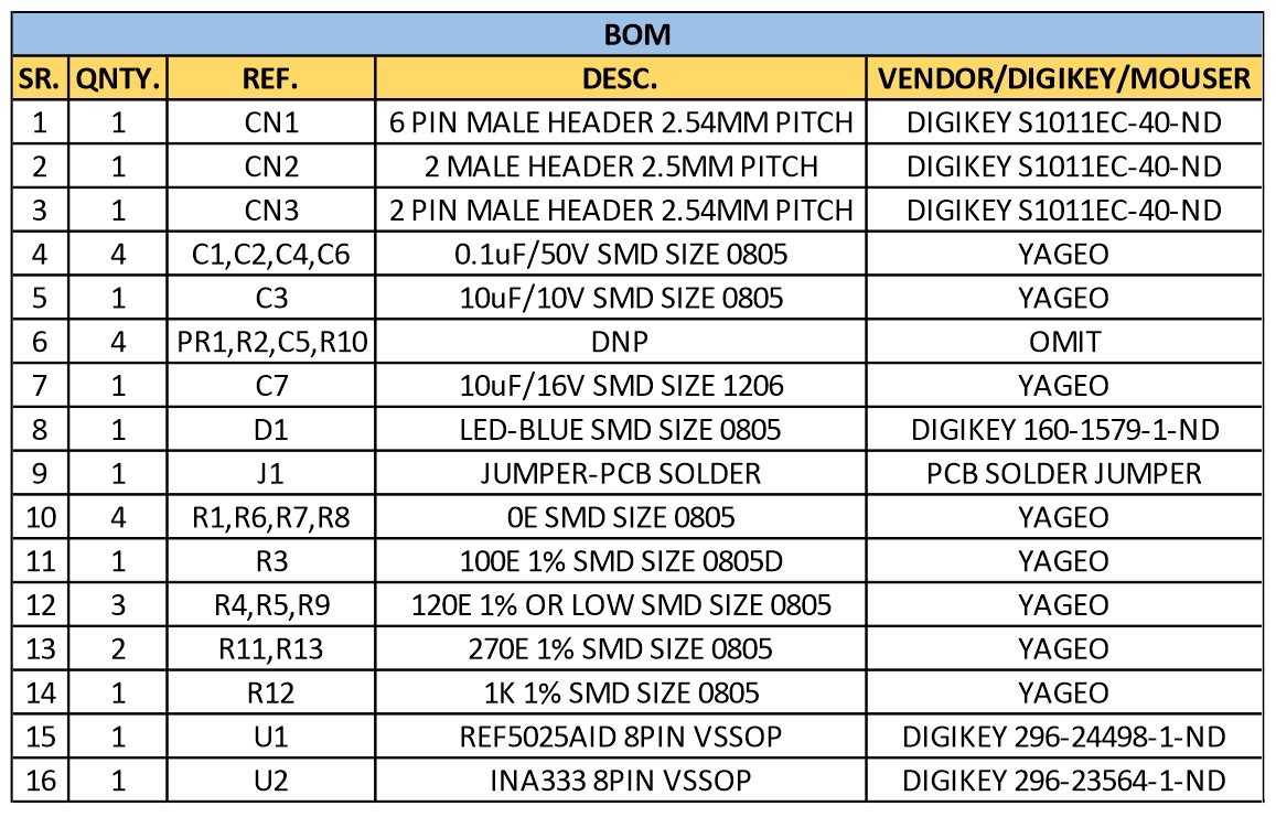
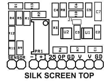
Parts List
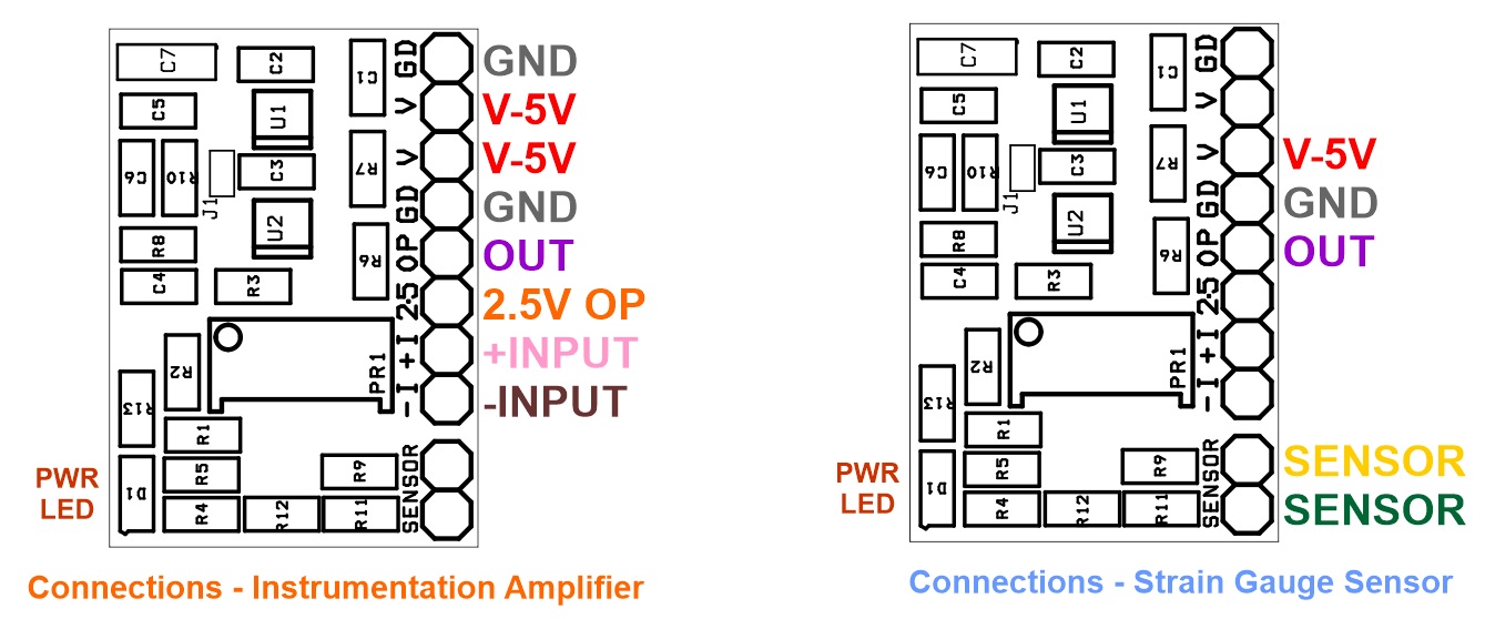
Connections
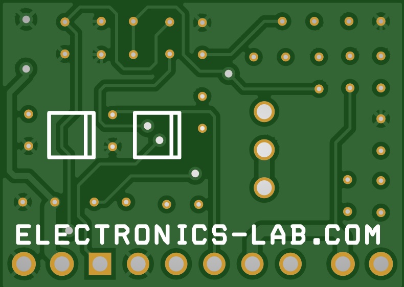
Gerber View
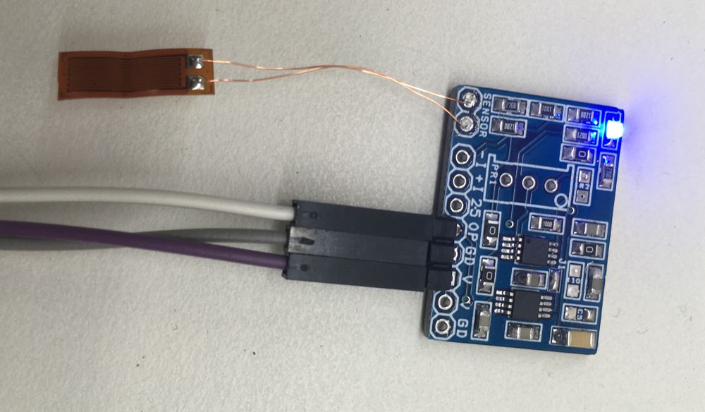
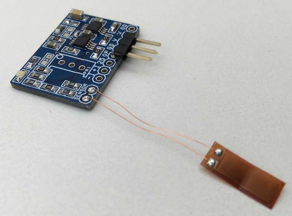
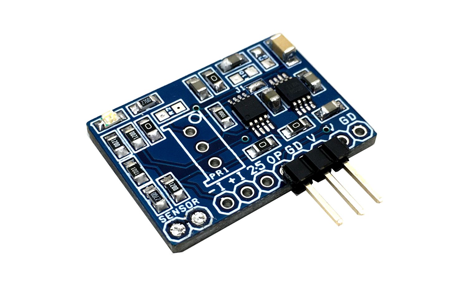
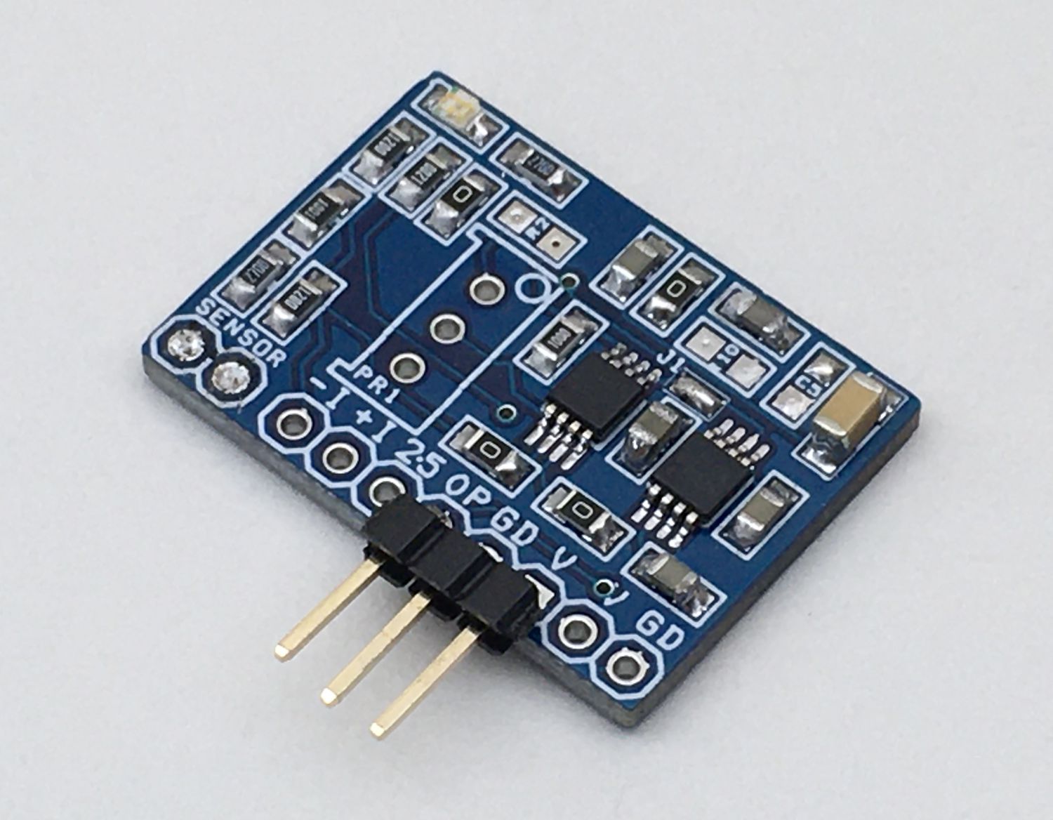
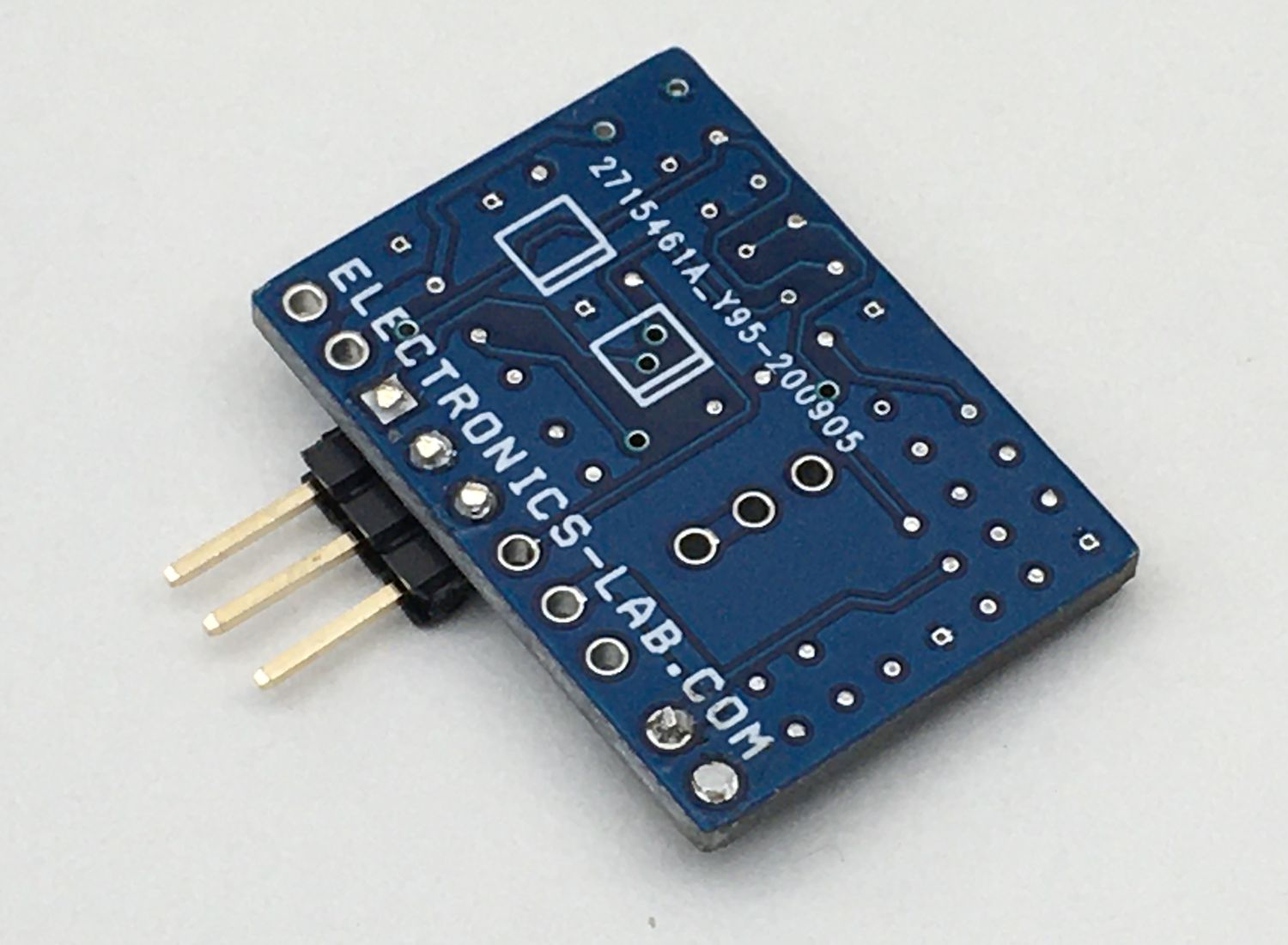
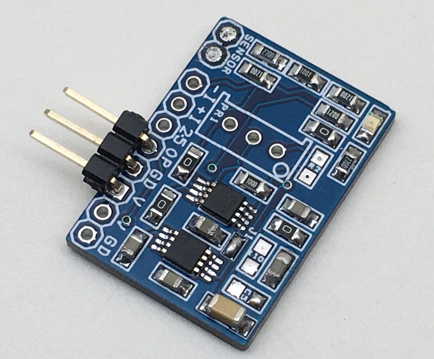
Photos
Video
INA333 Datasheet
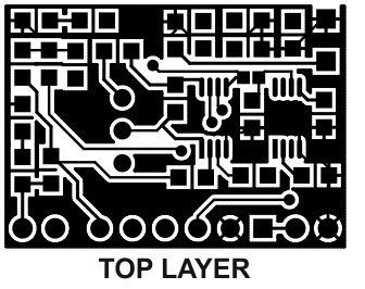
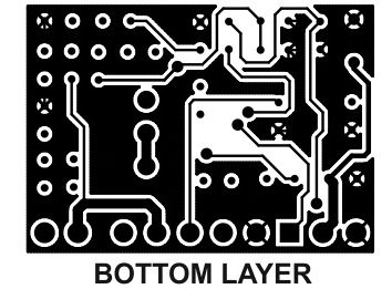
PCB
.png)


 to Single-Supply Signal Converter for ADC")
