

Binary Numbers
- Muhammad Shahid
- m_shahid@live.co.uk
- 73 Views
- 0 Comments
Binary Numbers
The binary numbers are expressed in the base-2 number system which has only two (2) distinct number values i.e. 0 and 1. Just like, most common, decimal numbers are expressed in a base-10 number system having ten (10) distinct numbers from 0 to 9. These number systems are designed to express information and binary numbers are used in the digital systems to carry out the flow of information in the form of zeroes and ones.
It is based on Boolean data type which has only two possible values i.e. true and false. It is named after the English mathematician George Boole and is now widely used in all digital systems. The Boolean represents a single bit whereas the binary number may consist of more than a single bit or Boolean value. As already said, a Boolean value may comprise of either “TRUE” or “FALSE” value and these values are also represented by “ON” or “OFF”, and” 1” or “0”, respectively. However, binary numbers are represented in “0” and “1”. In modern digital electronics, communication systems, computers, etc. the flow of information is in binary and a voltage level is designed to distinguish between 0 and 1 values.
The information carried by a digital system is discrete and represents a distinct voltage state or value at any instant of time. Unlike an analog signal or linear system, which has continuously varying values and is usually represented by an instantaneous value. In a digital system, binary values of 0 and 1 are given a voltage level so they can be distinguished during the flow of information. Most commonly, a value of 1 is represented by 5V, whereas, a binary value of 0 is given 0V or ground potential. These binary numbers in digital systems are usually referred to as BITS (Binary DigiTS).

The process of information in form of binary numbers or bits requires only two values or voltages and one of them is at ground potential. This requires less circuitry and is ideal for use in digital systems. The binary values can be represented by any voltage and have designated logic levels. For each voltage value, there is a logic level i.e. LOW or HIGH logic. The voltage level is usually kept between 0 and 10V. Generally, a high voltage level represents a HIGH logic level and a low voltage (ground) level represents a LOW logic level.
The electronic circuits are classified into analog and digital circuits depending on the signal type.
Analogue Circuits
The analog circuit uses time-varying continuous signals and covers, theoretically, an infinite range of values over a period of time. The analog circuit can respond to an analog signal over a period of time, accordingly. The signal may cover a voltage range from positive to a negative value.
The following figure illustrates a continuously varying or analog signal behavior over a period of time.
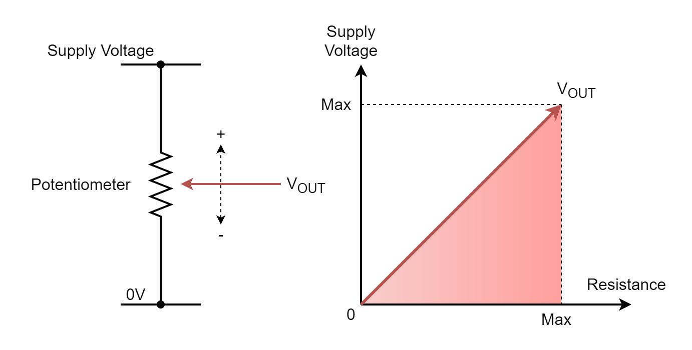
The output of the signal is taken from the potentiometer whose other ends are connected to extreme levels of the voltages i.e. supply voltage and ground. The knob of the potentiometer is rotated to vary the output resistance from zero to maximum value. The output voltage is obtained using a voltage division rule (VDR) and ranges from zero to supply voltage potential. Whilst slowly rotating the potentiometer’s knob, the output voltage gradually increases from zero to supply voltage potential and at every instant of time, a different value is obtained. Moreover, the gradual increase in output voltage indicates no sudden or step-change between any two periods. The plot of output voltage indicates the same i.e. no step change and is indicative of a continuous or analog signal. Examples of analog signals include sensor outputs from physical outputs such as temperature, light, pressure, distance, liquid levels, etc.
Digital Circuits
The digital circuit uses only two distinctive voltage levels for its HIGH and LOW logic levels. These HIGH and LOW logic levels correspond to the 1 and 0 values of binary, respectively. There will be only two voltage levels corresponding to these logic levels only at any instant or period of time. The voltage level for these logics may be different depending on the circuitry such as Transistor-Transistor Logic (TTL), Complementary Metal Oxide Semiconductor (CMOS), etc.
The digital signal and its discrete voltage levels can be explained by the following figure.
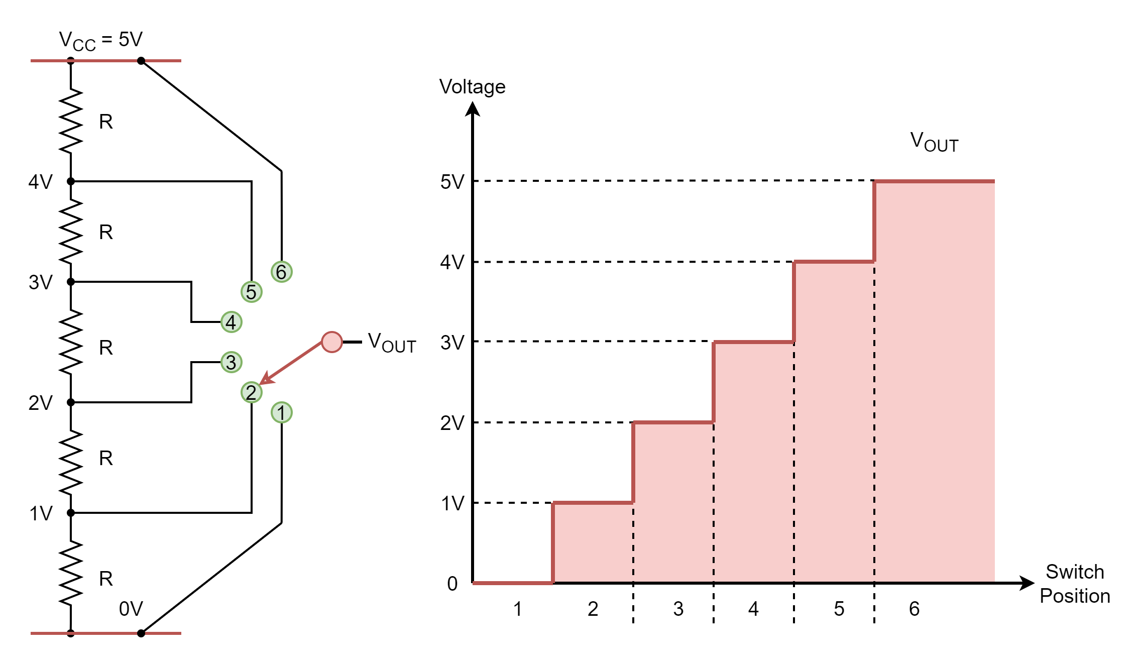
The potentiometer of the above circuit has now been replaced with five (5) resistors of equal values. The output voltage is taken from extreme voltages levels (5V and 0) as well as from each junction of resistors. These junctions form the voltage divider circuit and the inclusion of each resistor causes an increase in output voltage. The output voltage stages have been divided into six (6) stages and the knob connects the output to each of the stages sequentially. Moving from stage 1 to stage 6, it is observed that the output voltage suddenly changes at each step and produces a distinctive voltage level that does not vary. The output voltage plot depicts the same i.e. stage change produces a sudden voltage step and each stage has a constant or distinctive voltage level over the period.
It is eminent from the above illustrations that a continuously varying or analog signal is not constant over a period of time and may contain an infinite range of values over a period. In contrast, a digital signal contains distinctive values over a period of time. In order to understand the difference between these two signals, a real-time example of a light dimmer can be taken for an analog signal. The rotation of the light dimmer is continuous and not abrupt. On other hand, a switch (button) controls the light as a digital signal. The switch has only two distinctive states i.e. OFF or ON and the change between them is abrupt.
Most electronic circuits contain both analog and digital circuits dealing with the sensors. The conversion from analog to digital is required to convert sensors, reading data in analog, to digital values using an analog-to-digital converter (ADC). The digital values can be processed in digital systems, easily transmitted, and stored in memory devices. Likewise, a stored digital value from the memory or instruction can be converted to an analog value using Digital-to-Analogue Converter (DAC).
Logic Levels
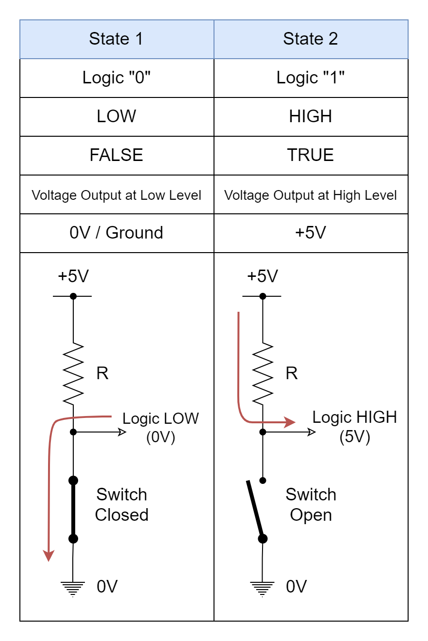
As discussed above in the article, a binary bit or Boolean value can hold only one of the two possible states i.e. logic 1 or logic 0. Logic 1 and logic 0 are also commonly referred to as ON/ HIGH and OFF/ LOW, respectively. In the following figure, these two states are shown along with simple circuits to achieve these possible states. The most commonly used logic family i.e. TTL uses +5V as indicative of logic 1 value.
Voltage Levels for TTL Devices
The digital logic levels i.e. HIGH and LOW are obtained from the signal voltage level and usually for a logic level a range of voltage is used depending on many factors. In the following figure, the input and output voltage levels of Transistor-Transistor Logic (TTL) are shown.
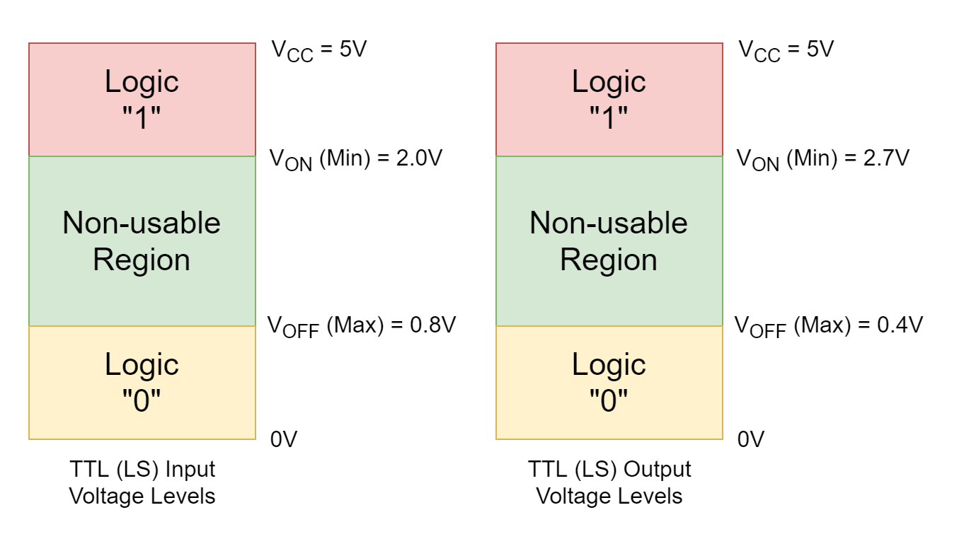
For the TTL input signals, a maximum of 0.8V is desired in order to ascertain a logic LOW, and a minimum voltage of 2V is desired for a logic HIGH. This means that any logical LOW input needs to have a voltage from 0 to 0.8V and from 2 to 5V for a logical HIGH input. The voltage from 0.8 to 2V is designated as non-usable. Likewise, for a TTL output signal, a logic LOW limit is set to a maximum of 0.4V, and a minimum limit of 2.7V is set for logic HIGH. The voltages falling within these voltage levels will be logically designated as HIGH or LOW depending on the voltage of the signal.
Conclusion
- The binary number is a base-2 numbering system in which each successive bit doubles the values of the binary number (power of two).
- Each digit of a binary number commonly referred to as bit is of Boolean data type and can hold one of the two possible values i.e. 0 or 1. The values of 0 and 1 are also designated as LOW and HIGH, respectively.
- Each successive bit of a binary number doubles the value of the binary number e.g. for 1,2,3,4, and 5 digits binary numbers the decimal value will be 1,2,4,8,16, and 32, respectively.
- The electronic circuits can be divided into analog and digital circuits. The analog signal is continuous and contains many values within a time period. Whilst, the digital signal has discrete values and change between these discrete values is sudden or abrupt.
- The most commonly used Transistor-Transistor Logic uses voltage levels of 0 and 5V for designating logic LOW and HIGH, respectively.
Please follow and like us:
Subscribe
Login
0 Comments


