Leaderboard
Popular Content
Showing content with the highest reputation since 03/18/22 in all areas
-
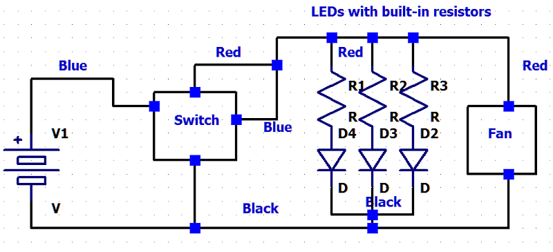
I believe this is what you need: push botton switch.asc push botton sw.xcf
 1 point
 -

I just do a design of lm386-based audio amplifier circuit
erinxie reacted to loribennms for a topic
thank you so much for your suggestion1 point -
Good to know that you got it working.1 point
-
You can add a decoupling capacitor. Sometimes, the output waveform can be clipped due to noise in the power supply. Adding a decoupling capacitor between the power supply and the ground can help reduce the noise and improve the output waveform.1 point
-

How a Power Quality Meter works and why it is so Important
Bobfadi reacted to James Franklin for a topic
Well Power quality monitoring is important because it will help officials to understand about the quality, power of electricity for a safe regular process. It tells official about the electrical current flow and its quality. For more information visit our blog https://sfere-elec.net/products/Power-Quality-Monitoring-20.html1 point -

DIY - ARDUINO BASED CAR PARKING ASSISTANT
Ashish Adhikari reacted to bidrohini for a topic
I really like this circuit. Such a small and compact PCB.1 point -

BGA rework Process?
Moises Campos reacted to HarryA for a topic
Is Rolling Meadows, IL 60008 near you? see: https://www.solder.net/training-courses/bga-rework-training/ See for low key diy rework: https://www.instructables.com/BGA-rework/1 point -

Need help in project development
Varun Flores reacted to Nancesar for a topic
Hi friends. I'm still quite new to this business, but now I'm writing a project that will allow real-time temperature monitoring. So far, this is at a theoretical stage and needs your advice and experience. I'm using a MLT028Q40-5 TFT display with a controller through the driver and it works great. I need help with data to import from an NTC temperature sensor.1 point -
Hall Sensor Bypass for Coffee Grinder
millicurie999 reacted to HarryA for a topic
I gather the machine has a fixed number of pulses it expects for each type of brew. It counts these via the two magnets. It also monitors the current draw by the motor. If the motor current drops off (no longer grinding) while it has not reach its count of rotations it "thinks" it is out of beans. If it is not out of beans and the motor is really working then it is missing counts at the hall effect sensor is what you are thinking? If it is really is out of beans it would discard the grounds that it has so far also? On second thought if it is missing counts it would run longer and grind to much coffee. So it must be that there are more counts to go and the current to the motor has fallen off?1 point -

We had an idea and its now a helpful product: ProBUDDY Kits
Jacquelyn Norris reacted to sundayrobotics for a topic
Breadboards, arduinos, cables.. We all love and work with those but when they are connected together as the hardware of our projects, it can get messy. To help all of us at that point, we've created a solution, first we used it, then sent prototypes out for review and then its now live on Kickstarter waiting for you to reserve yours: ProBUDDY Kits. Here is how it works: The hardware is taken on to our Base Plates and get fixed with special magnetic holders called ProBUDDY's. Then its so easy to work on, carry, store, demonstrate your projects. You can retrieve the components easily for another project. You can store your projects on any vertical (yes!) surfaces and keep your desks clean. And there are more. Here I want to share the Kickstarter link, thank you all for your support; https://www.kickstarter.com/project...y-kits-build-carry-store-your-projects-easily Best Sunday Robotics Team1 point -
Electronic flourescent tube starter
Soren Thompson reacted to HarryA for a topic
I am confused with the two SIDACs (Silicon Diode for Alternating Current) in series. They are rated 220-250 volts switching each. 240 mains voltages would be in the order of 340*1,4 or 480 volts peak. About the same as the two SIDACs; not much to switch with? "These tasks of the starter are taken over by two 135 V sidac (or a single 270 V one). The starting voltage is thus 270 V, Which is below the peak value of the mains (about 340 V), but higher than the working voltage of a 20-40 W neon tube." see: https://circuit-diagramz.com/sidac-neon-tube-starter/ I will look at the circuit some more.1 point -
programming the atmega 328p microcontroller previous article on this subject
Elijah Green reacted to HarryA for a topic
If you look in the IDE at [tools] -> boards you will see the Nano and the Duemilanove. You will not see the port listed until you select the board and have a board or adapter connected. The Meg2560 has a different AVR microcontroller; an ATmega2560. If you search on Youtube for the FT232RL (the USB to serial/TTL Adapter) you will find numerous videos. Speaking of ports, the current port is shown in the IDE in [Tools] also in the Preferences file. The Preferences file can be found [file] -> Preferences. That brings up a pop up window containing the path to the file. Near the bottom of the file can be seen the comport listed in two places. Also in the Device Manager it is listed under Ports(COM & LPT). Device Manager is via [Windows] + [x]. Sometimes you can edit the Preferences file to bring the comport inline with the device port iIf the IDE gets confused. You may know this but others may not. (I screwed up the fonts by cut and past again)1 point -
Buck Converter Design
ElectronicsLabUser reacted to HarryA for a topic
As this chip is made by Analog and Analog owns LTspice simulator the circuit appears in the simulator and can be explored there. The circuit there is slightly different. Note it uses the FDS6680A mosfets. If you want 10 amperes make sure the mosfets can handle the current. Go here and put in your requirements then you will see some 10 ampere chips: https://www.analog.com/en/parametricsearch/11491#/p5573=min|24&p5574=100|max&p5347=min|12&p5357=12|max&p5349=10|240&qsfv=vinmin|24_vinmax|100_vout|12_iout|10&p5362=Buck 1 point
 -
We had an idea and its now a helpful product: ProBUDDY Kits
Jacquelyn Norris reacted to sundayrobotics for a topic
Are you ready for the SUPERBOWL?! We are! We present you the Reward 7, ProBUDDY Kits SuperBowl 2022 edition with limited time and pcs between February 11 2022 - February 15 2022. https://www.kickstarter.com/projects/sundayrobotics/probuddy-kits-build-carry-store-your-projects-easily1 point -

Good book for beginners?
KaneD reacted to charlesmox1 for a topic
By the way, thanks for the books, Perhaps someone can advise something relevant today?1 point -
Septic Service Oologah - Every A Septic Solutions employee receives continuing education on all types of septic systems to stay current on the latest technologies and products for your specific system.1 point
-

Sensor alarm and transmitter
Jacquelyn Norris reacted to steve10101 for a topic
Hey guys, I'm trying to make a proximity alarm and having trouble finding info. I can find plenty of examples for projects for an alarm and transmitter where as soon as the transmitter is a certain distance away the alarm flashes. What I'm wanting is the opposite, as soon as the transmitter is within a certain distance the alarm flashes. I'm sure this is as simple but I'm completely new to electronics so have no idea if its as simple as reversing a few things etc??? I don't even know the correct name for this product?? Any help or direction on this subject would be greatly appreciated. Cheers1 point -
Sensor alarm and transmitter
Jacquelyn Norris reacted to steve10101 for a topic
Hiya, I now cant find the projects I found yesterday sorry... but the below link is a device similar to what I'm looking for, but I'm looking to make this work in reverse (hoping this may help). The distance I'm trying to achieve would be for the alarm to activate if transmitter was anything from 0-10 feet away. http://www.pimall.com/nais/rdiftagalert.html1 point
