Search the Community
Showing results for tags 'home automation'.
Found 4 results
-
 Nowadays home automation is a trending topic among electronic enthusiasts and even the mass population. People are busy with their life challenges, so an electronic device should take care of the home instead! The majority of such devices need internet or Wi-Fi for connectivity or they don’t offer a user-friendly GUI, but I decided to design a standalone wireless monitoring/controlling unit that can be adjusted using a graphical and touch-controlled LCD display. The device consists of a panelboard and a mainboard that communicate using 315MHz (or 433MHz) ASK transceivers. The panel side is equipped with a high-quality 4.3” capacitive-touch Nextion Display. The user can monitor the live temperature values and define the action threshold (to activate/deactivate the heater or cooler), humidity (to activate/deactivate the humidifier or dehumidifier), and ambient light (to turn ON/OFF the lights). The mainboard is equipped with 4 Relays to activate/deactivate the aforementioned loads. To design the schematic and PCB, I used Altium Designer 23. The fast component search engine (octopart) allowed me to quickly consider components’ information and also generate the BOM. To get high-quality fabricated boards, I sent the Gerber files to PCBWay. I used the Arduino IDE to write the MCU code, so it is pretty easy to follow and understand. Designing a GUI using the Nextion tools was a pleasant experience that I will certainly follow for similar projects in the future. So let’s get started 🙂 Specifications Connectivity: Wireless ASK, 315MHz (or 433MHz) Parameters: Temperature, Humidity, Ambient Light Wireless Coverage: 100 to 200m (with Antennas) Display: 4.3” Graphical, Capacitive-Touch Input Voltage: 7.5 to 9V-DC (power adaptor connector) References article: https://www.pcbway.com/blog/technology/Wireless_Home_Automation_Control_and_Monitoring_Using_a_Nextion_HMI_Display_24d9be1d.html [1]: L7805: https://octopart.com/l7805cp-stmicroelectronics-526753?r=sp [2]: SMBJ5CA: https://octopart.com/rnd+smbj5ca-rnd+components-103950670?r=sp [3]: 78L05: https://octopart.com/ua78l05cpk-texas+instruments-525289?r=sp [4]: ATMega328: https://octopart.com/atmega328pb-anr-microchip-77760227?r=sp [5]: Si2302: https://octopart.com/si2302cds-t1-e3-vishay-44452855?r=sp [6]: LM1-5D: https://octopart.com/lm1-5d-rayex-53719411?r=sp [7]: Altium Designer: https://www.altium.com/yt/myvanitar [8]: Nextion Display: https://bit.ly/3dY30gw
 -
 I love mining and I truly believe that blockchain and digital currencies will one day change the world. Cryptocurrency has played a significant role in my life and has made me a morning person, ha ha. Miners require 24 x 7 access to the Internet. Recently, I went on a short business trip and my router for some stupid reason stopped working. I lost complete access to my home network and my miners. When I returned from my trip, my only aim was to fix this issue by creating an "Internet Hardware Watchdog" that reboots the router whenever something silly happens to it. Note: If you do any work with "mains power" such as 120v or 240v AC power wiring, you should always use proper equipment and safety gears and determine whether you have adequate skill and experience or consult a Licensed Electrician. This project is not intended for use by children. The Logic Let me first explain the logic to you. In a nutshell, in this setup I am going to ping "www.google.com" and as soon as the ping drops I will reboot the router. To achieve this, the NoduMCU first connects to the WiFi network and then pings 8.8.8.8 (www.google.com). If it receives a successful ping, one out of the 3 blue LED patterns is displayed. If the ping fails, 5 more retries are given before rebooting the router. The reason I am NOT rebooting the router straightaway is to avoid false positive ping fail responses. However, once the "fail_count" counter becomes 5, NodeMCU turns off the router by pulling the armature of the relay module. The armature of the relay is held for 15 seconds before releasing it so that the router is properly power cycled. Once the armature is released, the system waits for a minute before sending the next ping request. This gives enough time to the router to successfully perform its POST activities. The above steps are then endlessly repeated in the loop section of the code. Components Required For this project we need: NodeMCU Stepdown Converter Relay Module 2 x Red LEDs 3 x Blue LEDs 100Ω Resistor Power Plug and a Power Socket Schematic Now, let's put the components together exactly the way I have shown in the schematic diagram. Be very careful while handling AC Main Power sockets and cables. The Stepdown Converter powers the NodeMCU and the Relay Module. LEDs are connected to the Digital pins of the microcontroller. The relay acts as a switch and switches on or off the router based on the ping response. Please make sure you check the pins of your relay module before hooking it up to the circuit. The Board So, this is how my board looks like in 2D and 3D. I basically have created a replica of the NodeMCU Prototyping Board which you can buy from AliExpress for about $4 to $6. Components Assembly Lets start by soldering the NodeMCU to the board. Since I care a lot about my Sensors and Microcontrollers, I am not going to solder them directly to the board. Instead I am soldering 'female pin headers' to the board which will house all the sensors and the microcontrollers in them. I initially thought of soldering the LEDs directly on the board however something clicked in my mind and I went ahead and soldered them on a separate perfboard and then soldered the perfboard to the NodeMCU development board. Well, this was totally unnecessary. Once the LEDs were in place, my next step was to solder the step-down-converter and the relay-module to the board. If you want to know how I created this relay module, please check out my tutorial no. 19 DIY Relay Module : https://www.youtube.com/watch?v=3n69b4sdDjk the video and the blog post links are in the description below. Next, I made a hole in the transparent box and glued the power socket into it. Well I created a bit of mess while gluing the socket and accidentally glued the box on to my dining table, silly me. I also drilled a hole at the back of this box, for the cable that will connect to the AC Main power supply. Pretty much that's it. Once again, I would like to warn you guys: If you do any work with the "main power" such as 110v or 240v AC, you should always use proper equipment and safety gears and determine whether you have adequate skill and experience or consult a Licensed Electrician. This project is not intended for use by children. To conclude the setup, I added a small skull inside the acrylic box. This skull has been sitting on my desk just collecting dust for over a year, ha ha. The Code Now, let's have a look at the code. You can download the code and other resources from the links provided in the description below. To Run the attached code you need to download and install the "ESP8266Ping" library. You can either download it from GitHub or from the link provided in the description below. Unzip and copy the archive to the Arduino's Library Folder and change the board type to ESP8266 in the Arduino IDE and select NodeMCU. The code starts by including all the libraries and variables on top. Then in the setup() section I have defined all the pin modes and have made a connection to the WiFi router. In the loop() section I am performing a ping test and based on the test result I am either blinking the blue LEDs or power cycling the router. Thanks Thanks again for checking my post. I hope it helps you. If you want to support me subscribe to my YouTube Channel: https://www.youtube.com/user/tarantula3 Blog Posts: Internet Hardware WatchDog : https://diy-projects4u.blogspot.com/2021/12/internet-hardware-watchdog.html DIY Relay Module : http://diy-projects4u.blogspot.com/2020/08/diy-relay-module.html Video: Internet Hardware WatchDog : DIY Relay Module : https://www.youtube.com/watch?v=3n69b4sdDjk Other Resources: Code: https://drive.google.com/file/d/1HyTUMUBDK0neO854XMl3dyy5ceoeTImw/view?usp=sharing ESP8266Ping Library : https://github.com/dancol90/ESP8266Ping.git ESP8266Ping Library : https://drive.google.com/file/d/1uFfY5wW7-oWRNjP_XaBj2IM189M1n1FK/view?usp=sharing Schema: https://drive.google.com/file/d/1gn2ZhMp5Uz4YDv5GjxgIq1rtzh-21Rwe/view?usp=sharing Gerber File: https://drive.google.com/file/d/1l0bszJ0AV7S9s-y9jTWGcw9MrWayVJxZ/view?usp=sharing Flowchart: https://drive.google.com/file/d/1CL3g0nT1IZfdL8MZqN_PB-mKC9k_JfWH/view?usp=sharing Support My Work: BTC: 1M1PdxVxSTPLoMK91XnvEPksVuAa4J4dDp LTC: MQFkVkWimYngMwp5SMuSbMP4ADStjysstm DOGE: DDe7Fws24zf7acZevoT8uERnmisiHwR5st ETH: 0x939aa4e13ecb4b46663c8017986abc0d204cde60 BAT: 0x939aa4e13ecb4b46663c8017986abc0d204cde60 LBC: bZ8ANEJFsd2MNFfpoxBhtFNPboh7PmD7M2 Thanks, ca again in my next tutorial.
 -
Has this ever happened to you? You come back from a romantic dinner date and when you open the shutter door of your garage you realize that you left the garage light ON. You spent few hours outside with your partner to impress her and all the time this light bulb was on. You immediately turn around and look at her face to see a silent anger on her face. Alright, enough of that. So, in this tutorial, I am going to turn on and off the garage light using a PIR sensor. When the sensor detects a moving object, it turns on the light bulb and when the moving object is gone, it turns it off. Lastly, I am going to make sure that light bulb only turn on during the night time (when its dark). Step 1: Logic In this project, I will be using a PIR sensor along with an LDR to turn on or off a light bulb using a Relay. The things I need to consider before designing the circuit are: - The bulb should only turn on when the room is dark and when a motion is detected. - The bulb should turn off after 30 seconds of the object leaving the sensors proximity. - Most important, we need to place the LDR in a place where it doesn't turn off the bulb as soon as it lights up. Step 2: Hardware For this tutorial we need: A General Purpose PCB 2 x HC-SR501 PIR Sensor 2 x 1N4148 Small Signal Fast Switching Diodes 1 x 1N4007 High Voltage, High Current Rated Diode to protect the micro-controller from voltage spikes 1 x LDR 1 x 10K Trimmer Potentiometer 2 x 470 Ohms Resistor 1 x 10K Resistor 1 x 1K Resistor 1 x 2N3906 General Purpose PNP Transistor 1 x 2N2222 General Purpose NPN Transistor 1 x 5V Relay 1 x LED to display the status 5 x Terminal Blocks 1 x 220V to 5V Buck Step Down Module Few Connecting Cables And General Soldering Equipments Step 3: Assembly Lets first connect the LDR and setup the light detection bit. As we all know we need to setup a voltage divider to use the LDR in a circuit, so, I am adding this 10K POT and 470ohms resistor to setup the voltage divider bit. By adjusting the resistance of the POT we can adjust the intensity of sunlight at which this circuit will operate. Now, lets install the PIR sensor. Connect the VCC to +5v and GND to ground. Then connect the 1N4148 diode to the OUT of the sensor. In this circuit, I am installing just one sensor however in the actual project I have used 2 sensors to capture a bit more than 180 degrees. So, to avoid the sensors from back-feeding each other we need to install a diode to the OUT pin of each sensor. If you want to capture motion at 360 degrees you may need 3 to 4 sensor and diode pair to achieve that. Now that we have the PIR sensor and the LDR in place we need to add the 'AND' functionality. To achieve this I am adding a general purpose PNP transistor. When a motion is detected 'and' when the sunlight is at a certain intensity (adjusted by the POT) current flows out of the transistor. Next, we need to amplify the current received from the collector of the PNP transistor and turn on and off the LED indicator and the Relay. A general purpose NPN transistor is used to achieve this. That's it all done. Step 4: What Have I Have Made So, this is what I have made. On my board components are pretty much soldered everywhere, but you may like to have them nicely installed to give it a bit more cleaner look. OK, so lets check out how this works. Step 5: Demo Alright, I have placed the board on this table to do a quick test. I haven't hooked up a light bulb to the circuit yet. However, the LED indicator should serve the purpose of this demonstration. So, now I am going to turn off the light and make the room dark. Let's see if the sensor picks up motion and lights up the LED. Tada, it works. Now, lets turn on the light of the room and see if the LED indicator turns off or not. Yessss, that works. OK, finally just want to make sure that the light bulb turns off after 30 seconds of me moving out of the sensors proximity. Boom, and that concludes the project. I can now install it on the ceiling and make my partner happy. Instead of having 2 to 3 PIR sensors you can use one and install it at the corner of the wall. However, that will require a fair bit of wiring either inside the roof or on the ceiling, which will be way more expensive and tedious than installing 3 sensors an d putting the device in the middle of the room. You can also swap the Arduino with a NodeMCU board and do a remote data logging to log the time when the sensor detected motion or when the light went on to record when people entered your garage and how long they stayed in there. Step 6: Areas of Applications of PIR Sensors This setup can be used to: * Automate All Outdoor Lights * Automate Lights of Basement, Garden or Covered Parking Areas * Automate Lift Lobby or Common Staircases Lights * Automate bedside or night lamp * Create a Smart Home Automation & Security System and more.. Step 7: Thanks Thanks again for watching this video! I hope it helps you. If you want to support me, you can subscribe to my channel and watch my other videos. Thanks, ca again in my next video.
-
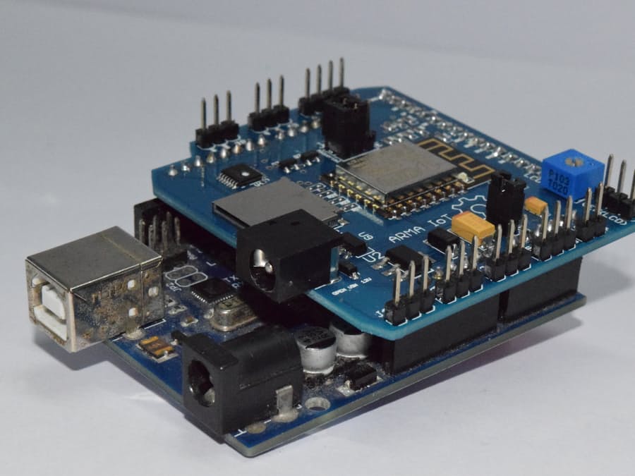
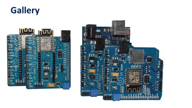
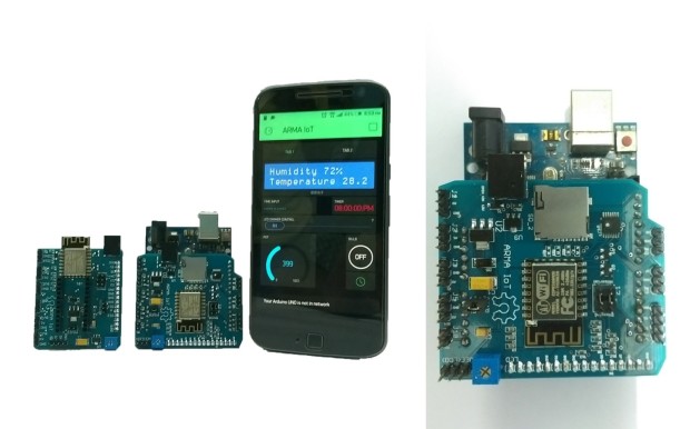
Are u looking for a way to connect the Arduino to the internet easily? Do you want to develop your IoT project quickly without much hassle? ARMA IoT might just be the thing for you! The simple and efficient Arduino shield is powered through a esp12f wifi module, which enables it to be connected to the wifi network. it also has an SD card slot for for extra data storage like its wired brethren the Ethernet Shield. The ARMA IoT goes a step further and provides an easy plug and play feature for most of the common devices such as sensors, motors, LCDs and relays. The ARMA IoT is a great place for beginners to start their IoT project, as it requires minimum time to setup the hardware all thanks to the plug and play feature. Even the programming is simplified through the help of apps such as Blynk, which provides easy feature of controlling the Arduino through your Android or iOS phone. Thingspeak an upcoming IoT platform is also supported by the shield. The ARMA IoT platform proves as a tool for aspiring beginners and also a prototyping tool for advanced users. IoT products can be developed much faster with the help of this board. Weather it is creating a simple IoT project such as blinking LEDs or controlling relays, or developing your own Home automation system, the ARMA IoT facilitates it all and things seem to happen rather quickly with all the features provided on the board. The wifi connection feature can provide fast communication between devices or two instances of ARMA itself, making it applicable for simple swarm robotics, wireless controllers etc. The applications can also be extended to simple robotics, Energy management systems and it does not stop there as it all depends upon the users creativity. To get started simple tutorials are provided on the YouTube page of ARMA IoT, the link below guides on the setup of Arduino and ARMA IoT with the help of Blynk app More tutorials and projects will be posted to help you make the most of the shield. Of Course there are also various DIY communities that can provide you with both support and inspiration for your upcoming IoT projects. thus ARMA is another simple board that has the ability to bind many devices together. The ARMA IoT is still undergoing a crowdfunding campaign in Indiegogo and is available for pre-order. https://www.indiegogo.com/projects/arma-iot-breakout-board-for-arduino#/