

SafeBee – A GPS Tracker for Beehives
- Zak Kemble, Mike Papadimitriou
- https://zakkemble.net
- 3.017 Views
- advanced
- Tested
- SKU: EL88315
- Quote Now
This is an original design of a GPS tracker designed on Elab and it is intended to be used as a security device for beehives, but it is not limited to this. It can be used everywhere a motion-activated GPS tracker is needed, like your car, bike, or even your boat. It is a GPS tracker controlled by simple SMS commands and designed for reliability, low power consumption, and ease of use. It features a MEMS accelerometer that is used to intelligently detect movement and once triggered it will power on the GPS module and will try to acquire the current coordinates. The location details will be transmitted to the owner’s smartphone via a simple SMS and then follow update the coordinates at predefined intervals.
Key Features:
- Remote management via simple SMS commands
- High reliability – no need to babysit the tracker due to crashes and resets
- Long battery life – over 1 year standby on a single charge (2500mAh battery)
- 3-axis high-sensitivity MEMS Accelerometer
- Intelligent Triggering – it will not be triggered by accidental movement
- Selectable Trigger Sensitivity Level
Description of Operation
The tracker has 3 main modes of operation, detailed below:
- Standby
- Ready
- Tracking
Standby mode
In standby mode, the GSM and GPS modules are powered down and the microcontroller is in sleep mode, resulting in a current draw of approximately 70uA, mainly by the accelerometer (MMA7660). The accelerometer is used to detect movement caused by a possible thief. If the accelerometer is triggered 1 or 2 or 3 times (depending on the sensitivity level) inside of a 60-second window then the device will enter tracking mode. While in standby mode the tracker will also enter ready mode approximately every 12 hours, triggered by the microcontroller’s internal RTC. This is to check for incoming commands and battery status etc.
Ready mode
The ready mode is entered by the microcontroller’s internal RTC and when the tracker is first powered on. In this mode, the tracker will power up the GSM module and wait for any SMSs to come in and process them. The tracker will stay in ready mode for 5 minutes before returning to standby mode unless an SMS command has instructed the device to enter tracking mode (BEE+TRIGGER).
Tracking mode
Tracking mode is entered when manually instructed to by the BEE+TRIGGER command or after the accelerometer triggers (1 or 2 or 3 movements detect depending on sensitivity level) within a 60-second window, from either standby or ready modes. In tracking mode, the tracker will power up both the GSM and GPS modules and begin to send tracking alert SMSs to the number configured by the BEE+NUMBER command. The device will continue to stay in tracking mode until the BEE+CLEAR command is received or while the accelerometer is detecting movement and/or the GPS module has a lock and the speed is greater than 10KPH. If neither of these conditions is met for 6 minutes then the tracker will send a tracking stopped SMS and return to standby mode, or ready mode if the RTC was triggered within the last 5 minutes.
Power up and Battery Status
In ready and tracking modes if the battery voltage falls below the threshold voltage (3650mV default) then a low battery alert SMS will be sent to the number configured by BEE+NUMBER. Approximately every 30 days (60 RTC triggers) an automated status SMS is also sent to the number configured by BEE+NUMBER.
When power is first applied to the device the tracker will be in ready mode and it will check for incoming SMS and then go to sleep. This is the ideal time to configure the tracker with the BEE+NUMBER number. This is the number that tracking messages, monthly status reports, and low battery alerts will be sent. The phone number is stored in the microcontroller’s FLASH memory and it will be permanently saved, even if battery power is removed. At power-up, the tracker will send a status SMS and also ignore any movement detected by the accelerometer for the first 60 seconds.
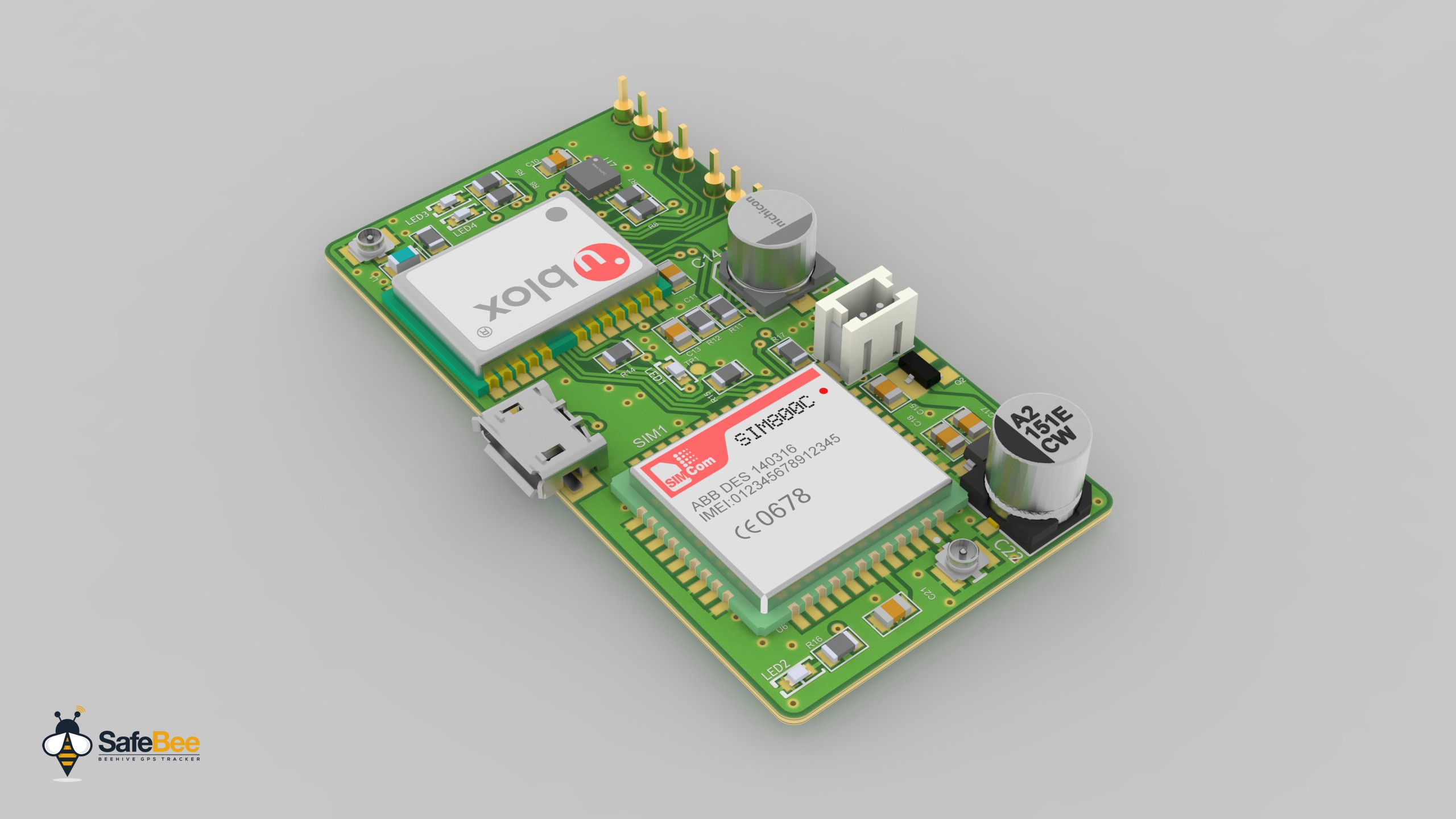
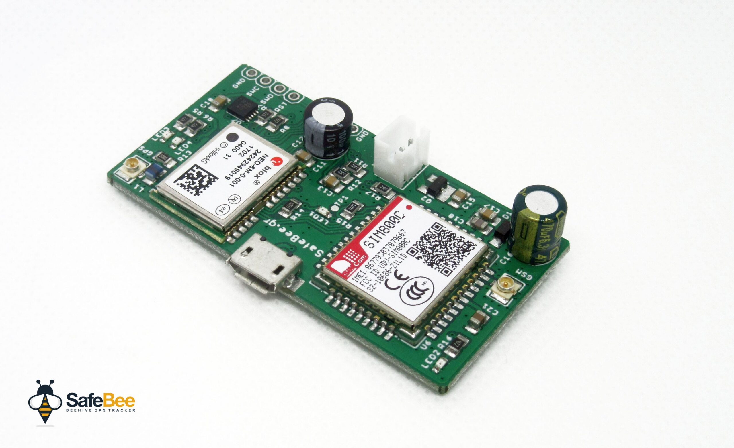
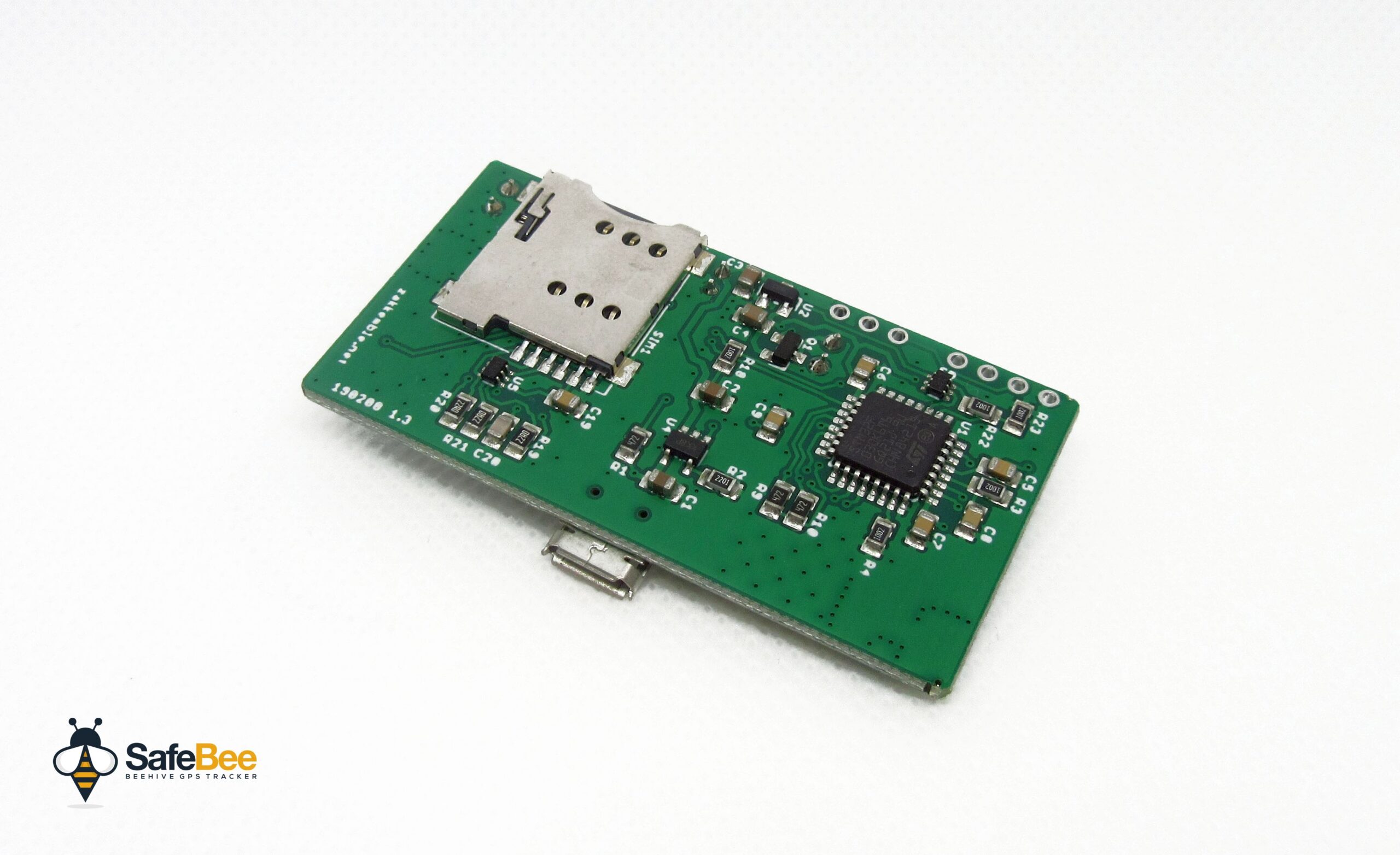
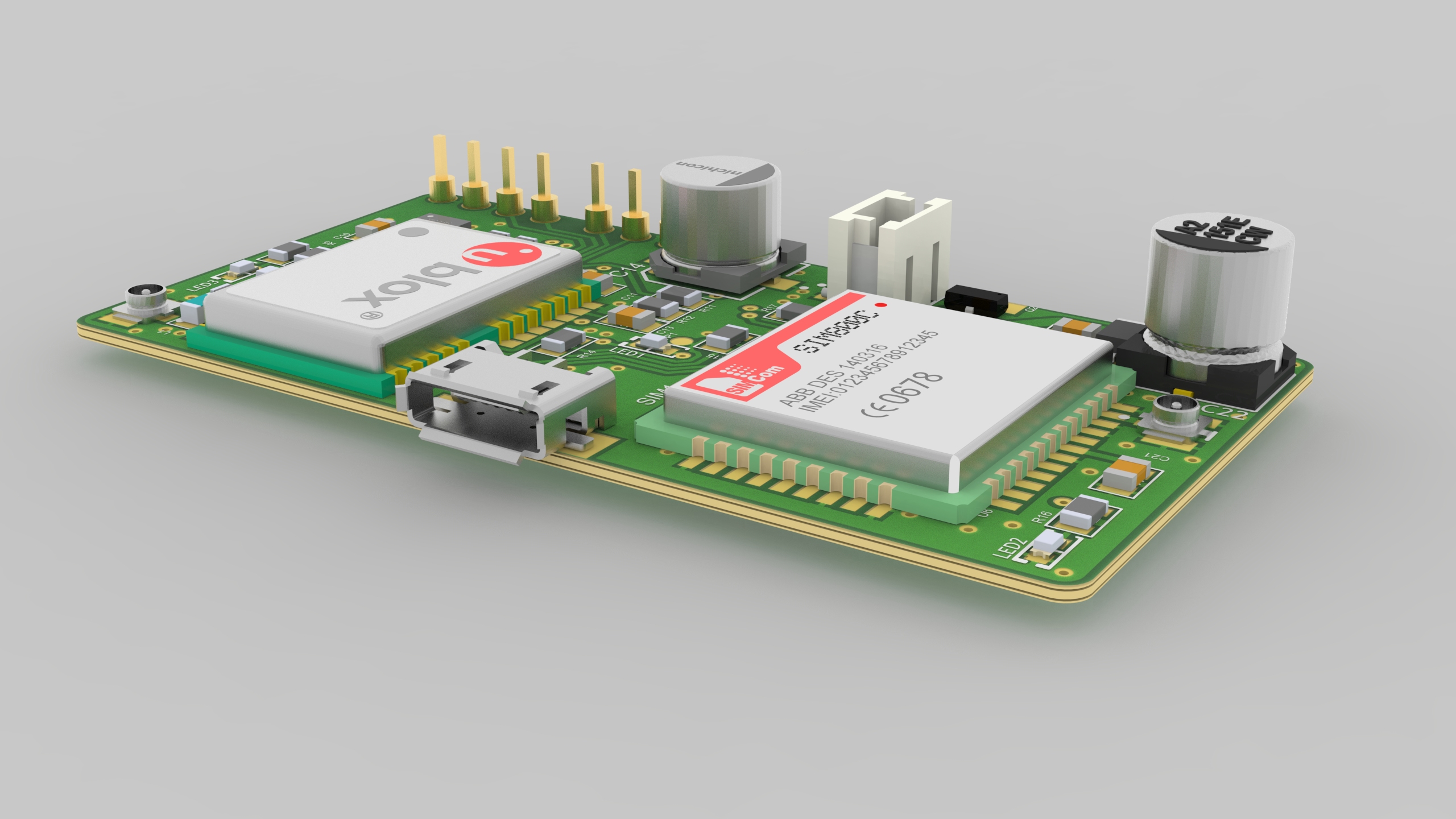
The Hardware
Hover images for details
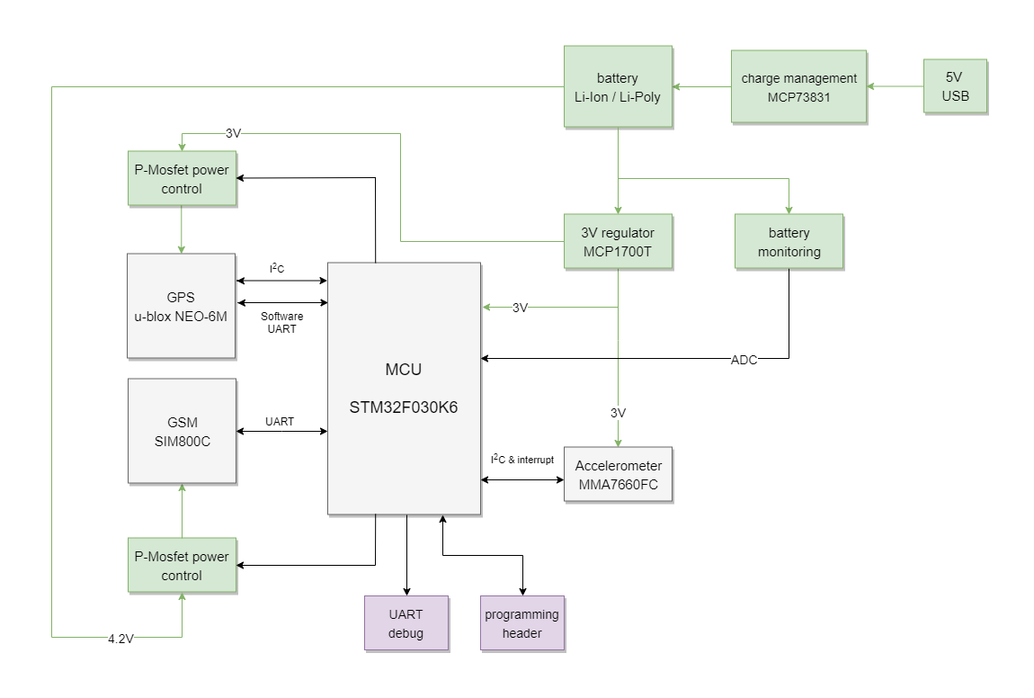
Block Diagram
MCU
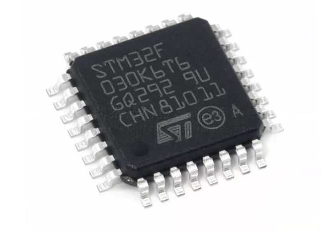
The tracker uses an ST STM32F030K6 microcontroller (ARM Cortex-M0, 32-bit RISC core), with 32KB of flash, and 4KB of RAM, and operates at up to 48MHz. The STM32F030K6 microcontroller operates in the -40 to +85 °C temperature range from a 2.4 to 3.6V power supply. A comprehensive set of power-saving modes allows the design of low-power applications. Currently, the firmware is taking roughly 24KB of flash (with debugging output enabled) and 1.7KB of RAM. The microcontroller is running at 8MHz and is supplied with 3V.
GSM module
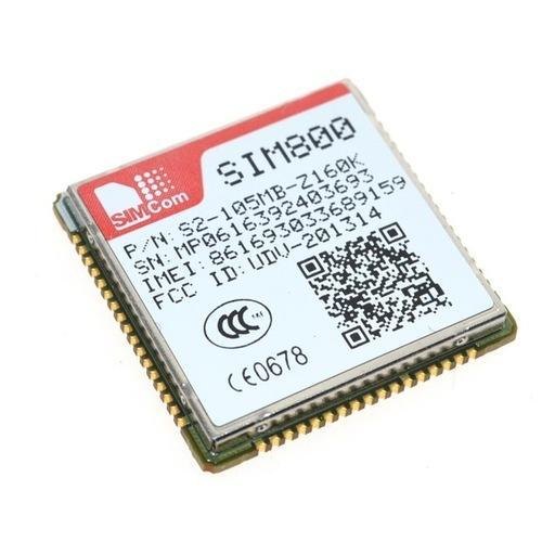
The GSM module is a SIMCom SIM800C and uses the UART bus to communicate with the MCU. The GSM module is power-gated with a P-MOSFET, controlled by the MCU, as its own low-power modes are not sufficient for this project. SIM800C supports Quad-band 850/900/1800/1900MHz, it can transmit Voice, SMS and data information with low power consumption. With a tiny size of 17.6*15.7*2.3mm, it can smoothly fit into our small board. The module is controlled via AT commands and has a supply voltage range 3.4 ~ 4.4V.
GPS module
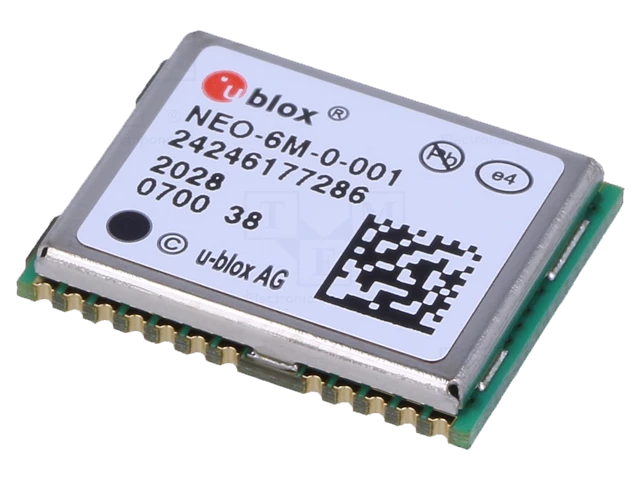
The GPS module is a u-blox NEO-6M and uses the I2C bus to communicate with the MCU. There is also a UART connection to the microcontroller as a fallback if the I2C interface does not work (usually the case with Chinese fakes). So, the tracker will work with the original NEO-6M as well as Chinese fake modules. The microcontroller implements the UART interface in software (via timer interrupts), operating at 9600 baud. The GPS module is power-gated with a P-MOSFET, controlled by the MCU, as its own low-power modes are not sufficient. The NEO-6M is powered in the range of 2.7 – 3.6V and has a size of 12.2 x 16 x 2.4mm. More details and design considerations can be found in the Hardware Integration Manual of NEO-6 GPS Modules Series and u-blox 6Receiver Description.
Supported GPS modules:
- U-blox NEO-5M
- U-blox NEO-6M
- U-blox NEO-7M
- U-blox NEO-M8N
- Various Chinese fakes using AT6558 and similar (if the PCB footprint is the same then it will probably work)
Accelerometer

The accelerometer IC is the MMA7660FC and uses the I2C bus to communicate with the MCU. The MMA7660FC is a ±1.5 g 3-Axis Accelerometer with Digital Output (I2C). It is a very low power, low profile capacitive MEMS sensor featuring a low pass filter, compensation for 0g offset and gain errors, and conversion to 6-bit digital values at a user-configurable sample per second. In OFF Mode it consumes 0.4 μA, in Standby Mode: 2 μA, in Active mode 47 μA and is powered in the range 2.4 V – 3.6 V. The accelerometer is always active, set up to create an interrupt whenever a shake or orientation change is detected, and is configured with a sampling rate of 8Hz (higher sampling rates improve detection, but also increase power consumption). The interrupt will wake up the microcontroller, where it will run through the main loop. In this loop it checks the interrupt status, and if set it will clear the interrupt and increment a counter at a maximum of once per second. The counter is reset every minute. If the counter reaches 3 the tracker is activated.
Battery Charger

The Li-Ion battery charging IC is MCP73832, which has a user-programmable charge current and the battery charge rate is set to 450mA. It includes an integrated pass transistor, integrated current sensing, and reverse discharge protection. It is usually recommended to charge Lithium batteries at no more than 0.5C, so the recommended minimum battery capacity to use with the tracker is 900mAh.
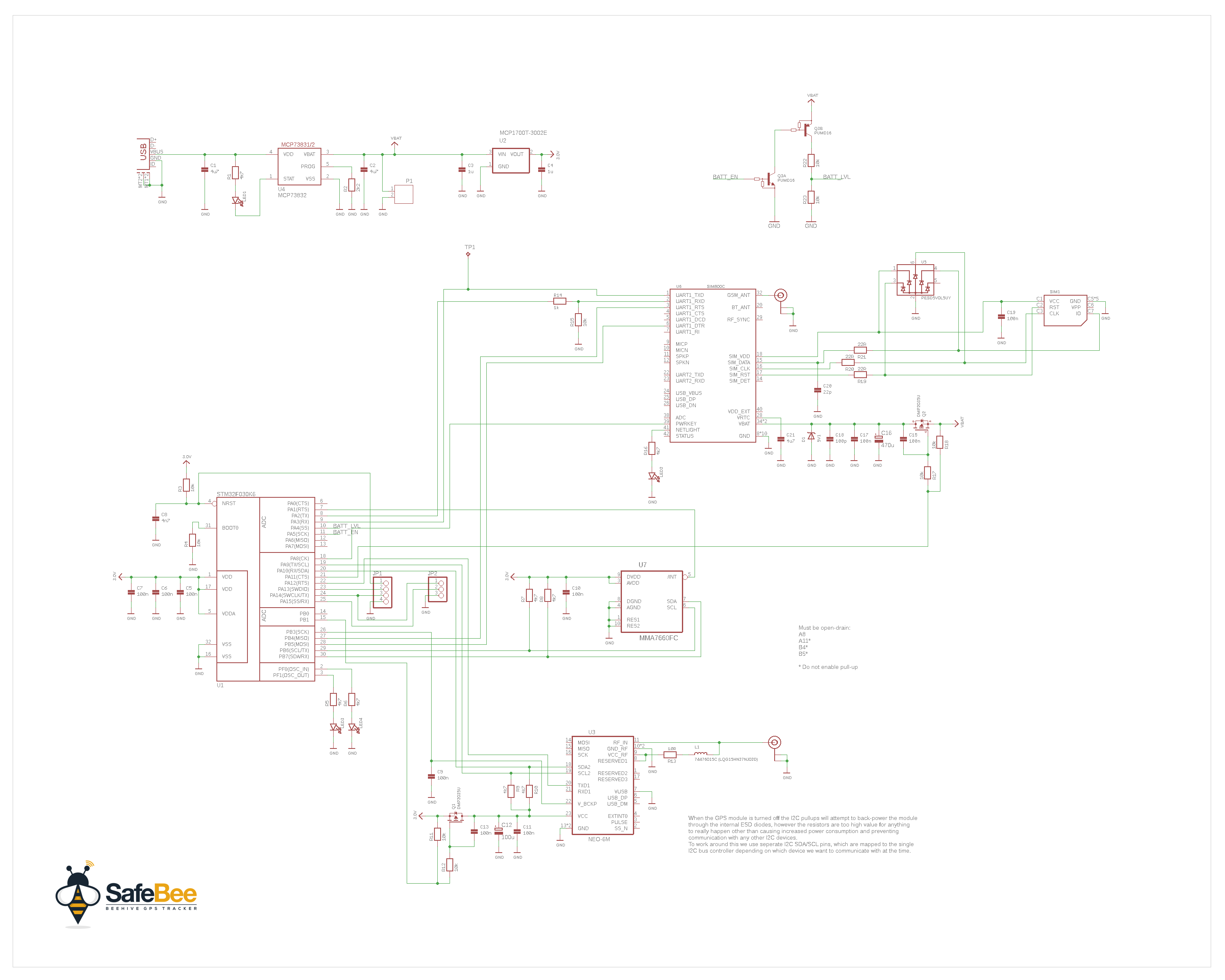
Schematic
 Parts List
| Item | Ref. | MPN | LCSC.com | Quantity |
|---|---|---|---|---|
| 1 | R1, R5, R6, R7, R8, R9, R10, R16 | 0805W8J0472T5E | C26022 | 8 |
| 2 | R2 | CR0805J80222G | C101970 | 1 |
| 3 | R3, R4, R11, R12, R15, R17, R18, R22, R23 | RC0805JR-0710KL | C100047 | 9 |
| 4 | R13 | RTT0510R0FTP | C103925 | 1 |
| 5 | R14 | 0805W8J0102T5E | C25623 | 1 |
| 6 | R19, R20, R21 | RC0805JR-0722RL | C108406 | 3 |
| 7 | C1, C2, C21 | CL21A475KAQNNNE | C1779 | 3 |
| 8 | C3, C4 | CC0805KKX7R8BB105 | C91186 | 2 |
| 9 | C5, C6, C7, C9, C10, C11, C13, C15, C17, C19 | TCC0805X7R104K500DT | C282732 | 10 |
| 10 | C8 | CC0805KRX7R9BB472 | C107153 | 1 |
| 11 | C12 | SS-101M1ASA-0605 | C311676 | 1 |
| 12 | C16 | DON’T PLACE | DON’T PLACE | 0 |
| 13 | C18 | 0805CG101J500NT | C82028 | 1 |
| 14 | C20 | 0805CG220J500NT | C24658 | 1 |
| 15 | Q1, Q2 | DMP2035U-7 | C110499 | 2 |
| 16 | Q3 | PUMD13,115 | C193171 | 1 |
| 17 | U1 | STM32F030K6T6 | C46830 | 1 |
| 18 | U2 | MCP1700T-3002E/TT | C62244 | 1 |
| 19 | U3 | DON’T PLACE | DON’T PLACE | 0 |
| 20 | U4 | MCP73832T-2ACI/OT | C38066 | 1 |
| 21 | U5 | PESD5V0L5UY | C330093 | 1 |
| 22 | U6 | SIM800C 24Mbit | C69119 | 1 |
| 23 | U7 | MMA7660FCR1 | https://www.aliexpress.com/item/32834701234.html | 1 |
| 24 | LED1, LED2, LED3, LED4 | FC-DA1608HRK-620D | C84263 | 4 |
| 25 | D1 | BZT52H-B5V1,115 | C179375 | 1 |
| 26 | L1 | AISC-0805-R056J-T | C186956 | 1 |
| 27 | GPS/GSM Antenna connector | U.FL-R-SMT-1(80) | C88374 | 2 |
| 28 | SIM1 | Micro SIM Slot | https://www.aliexpress.com/item/32786308183.html | 1 |
| 29 | USB | micro USB socket 5pin | https://www.aliexpress.com/item/32768317385.html | 1 |
| 30 | P1 | JST 2PIN CONNECTOR | https://www.aliexpress.com/item/5-SETS-Mini-Micro-JST-2-0-PH-2-Pin-Connector-plug-with-Wires-Cables-120MM/32711927418.html | 1 |
Battery Life
With a 2500mAh battery, standby current of 70uA, and waking up every 12 hours for 5 minutes with an estimated average current of 15mA the battery life should be approximately 1.5 years. A poor GSM signal can reduce battery life.
Status LEDs
| LED | Description | States |
|---|---|---|
| LED1 | Battery charging state | OFF: Battery not charging (no USB power or battery fully charged) ON: Charging |
| LED2 | GSM state | OFF: GSM is powered off FAST BLINK: GSM is not connected to a network (usually no signal or no SIM) SLOW BLINK: GSM is connected to the network |
| LED3 | MCU Operating mode | OFF: Standby mode ON: Ready or tracking mode |
| LED4 | GPS state | OFF: GPS is powered off FAST BLINK: GPS is acquiring a lock SLOW BLINK: GPS has a lock |
SMS Commands
| Command | Description |
|---|---|
| BEE+STATUS | Returns battery voltage - temperature - GSM signal strength - tracking enabled - is tracking - last GPS coordinates -sensitivity level. |
| BEE+CLEAR | If the tracker has been triggered this will clear it and stop tracking until the next trigger. |
| BEE+TRIGGER | Manually trigger tracking (will trigger even if disabled with BEE+DISABLE). Tracking will stay enabled until BEE+CLEAR is received. |
| BEE+ENABLE | Enable tracking triggers |
| BEE+DISABLE | Disable tracking triggers. |
| BEE+NUMBER=0123499988 | This sets the mobile number to send tracking - low battery warning and monthly status SMSs to. Other command replies are sent to the number that the command was sent from. |
| BEE+NUMBER=+441234999888 | International numbers must start with + then the country code. |
| BEE+SENSE=1/2/3 | This is the sensitivity level - 1 high sensitivity - 2 medium sensitivity - 3 low sensitivity. |
SMS SENT BY THE TRACKER
| SMS | Format | Example |
|---|---|---|
| Status (BEE+STATUS and automated status) | BAT: (batt level)% (batt voltage)mV (low batt thres mV) TMP: (temperature)C TRK: (is tracking) ( SIG: (signal)/31 GPS: (status) (lon,lat - speed KPH - time date) NUM: (SMS number) SEN: (Sensitivity Level) | BAT: 90% 4020mV (3650mV) TMP: 23C TRK: Y (Y) SIG: 18/31 GPS: LOCKED (11.12345,8.05234 - 64 KPH - 23:10:09 18-09-21) NUM: 01234567890 SEN: 1 |
| Tracking | TRK: (status: LOCKED | NO LOCK | STOP) https://maps.google.com/maps?q=loc:lon,lat - speed KPH - time date | TRK: (LOCKED) https://maps.google.com/maps?q=loc:11.12345,8.05234 - 64 KPH - 23:10:09 18-09-21 |
| Low Battery | LOW BATTERY: (battery voltage)mV (threshold voltage mV) | LOW BATTERY: 3400mV (3650mV) |
Programming
The device firmware can be programmed via the SWD interface, which is the 4-pin programming header on the PCB marked RST (reset), SWD (SWDIO), SWC (SWCLK) and GND (ground). An ST-LINK/V2 USB adapter is needed to program the device, which is available from ebay, aliexpress, and other places for less than £3.
3D Render
Debugging
Debugging data is sent out of the UART interface through the TX pin of the debugging header on the PCB, at 115200 baud. This pin is also shared with the SWD interface (SWC). The RX pin is unused but made available for possible use in the future.
Format
(<time>)(<module>)<message>
“time” is in milliseconds and only increments while the microcontroller is not in standby mode. “module” is either “DBG” (general messages), “TRK” (tracker), “GSM”, “GPS”, “SMS”, “MGR” (MGR is the SMS manager which controls when queued SMSs are sent, retried etc.)
START
SafeBee Tracker
http://zakkemble.co.uk
FW: 1.0.0 180407 (Built: Apr 7 2018 16:38:32)
(1634)(TRK)CONFIG
(1636)(TRK)Number: (Type: 129) "0000000000"
(1640)(TRK)Track interval: 180
(1643)(TRK)Wake duration: 300
(1647)(TRK)Trig idle: 360
(1649)(TRK)Low batt thres: 3650
(1654)(TRK)TRIG SECS: 1
(1657)(GSM)** ON **
(4000)(GSM)** POWERON **
(4502)(GSM)** CMDDELAY **
(4505)(GSM)CMD DELAY
(4507)(GSM)PWR SAVE OFF (5007)(GSM)CMD SEND
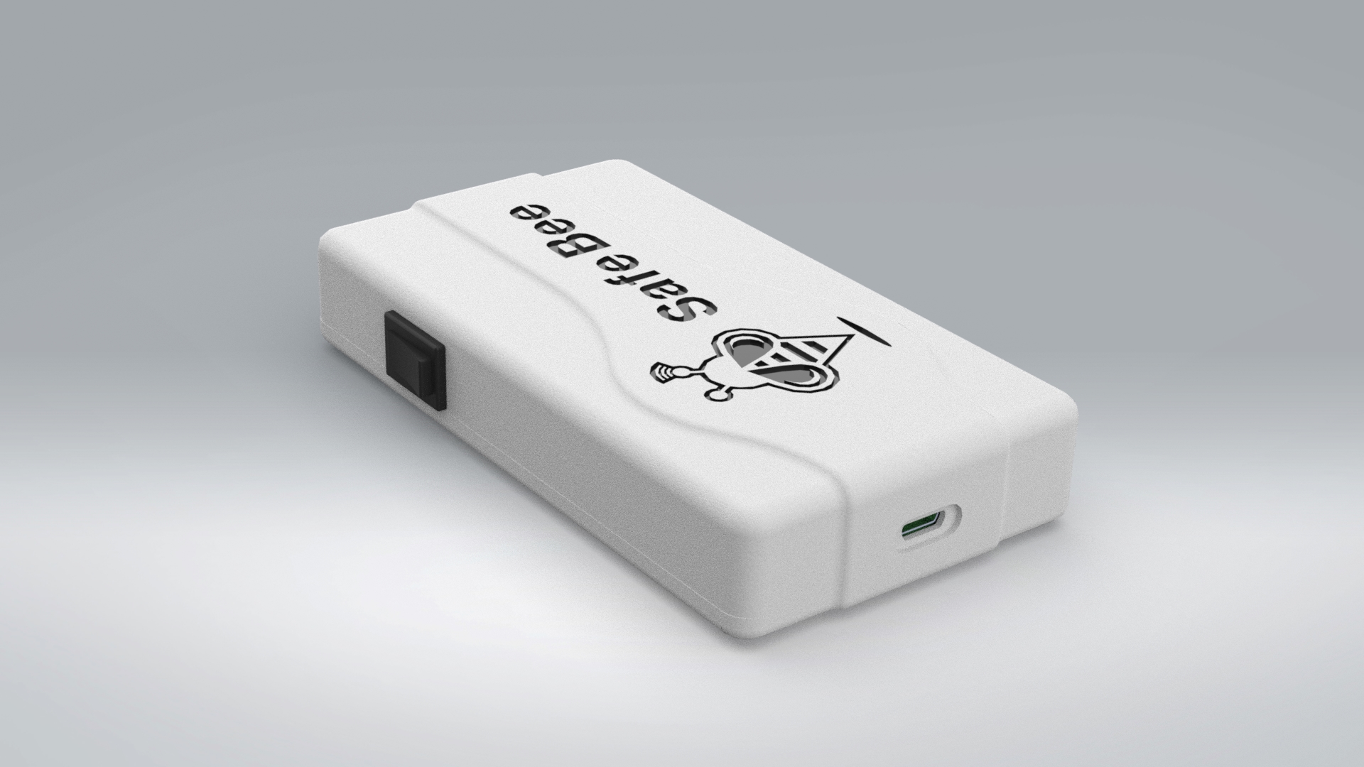
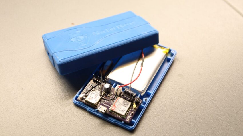
Enclosure
A 3D model of the enclosure is designed using Solidworks with overall dimensions of 60 x 20 x 112 mm. The enclosure has two holes, one for the charging micro USB connector and one to fit a mini rocker power switch. The provided design files (download .STEP and .STL files below) can be used to print your own enclosure in your desired color and material. The screws used to secure the enclosure are M3 x 10mm countersunk screws. Design is made by professional engineer janangachandima and you can find his services on the Fiverr page.

3D Enclosure View
Code
The source code and .hex file are available as a download below. Also, the Eagle design files are available.


.png)


Hi, There is no STEP and STL files.. How can e download? thank you
I’ve just uploaded the STEP and STL files above. Thanks
Thank you, I will keep the forum posted with the progress
You are much appreciated. Also, I have some ready boards on hand. Are you interested?
yes why not. I worked last almost 23 years with PIC assembly and a bit C codes. I choose that project because it will be first entry to STM32 world. It will be a big challenge form me. BTW, Are you Greek ? (the name) My family origin is from Ioannina wife family from Thessaloniki
We plan to sell this in our e-shop anytime soon. We have already manufactured a batch and I can ship you an assembled and programmed board for a pre-sale rate. Email me at info@electronics-lab.com and we can discuss this.
Hi Mixos,
What’s the part number of the SIM card socket ?
SIM Card socket is this: https://www.aliexpress.com/item/32786308183.html