All Activity
- Yesterday
-

Power Supply without "Power Saving Mode" -Seeking Advice on
HarryA replied to AJJJR's topic in Power Electronics
There are two types of USB power suppliers; the USB power supply and the USB power supply charger. It appears you are using the charger. Consider using a USB hub connected to the charger then connect your led/motion detector plus a simple LED device. The LED device would have a constant drain to keep the charger active? see for example(18ma). https://www.amazon.com/dp/B07RR3FQWF/ref=sspa_dk_detail_0?pd_rd_i=B07RR3FQWF&pd_rd_w=945qJ&content-id=amzn1.sym.0d1092dc-81bb-493f-8769-d5c802257e94&pf -
PROJECT to replace a MMBT3904 in a Lenovo G710
HarryA replied to crystallin's topic in Electronics chit chat
Comparing the two data sheets they appear to be nearly identical. the MMBT3904's higher current rating may make it last longer. -
 Yes, exactly! You are absolutely on point. Majority of the tech is just like you said or lighting for signage
 -
Shahnoor Beyondled joined the community
-
 Jack Rollin joined the community
 -
 omar Tremillo Avila joined the community
 -
I am so sorry, I can't open the FB link. Could you help send me a picture ? Or send picture to my e-mail: [email protected] Thank you.
-
 Raina Yin joined the community
 - Last week
-
 anettesmithh joined the community
 -
 Hi --I have purchased a USB LED light that come as part of a circuit that has a motion detector and a USB plug for power. I need to power this so it will be portable and thought a USB power supply would be the perfect thing. Problem is that when plugged in to a portable USB Power Supply and after it has turned the light on, set itself up and then turned the light off--to indicate it is motion detector mode--the power supply stops supplying power. I have tried two different power supplies and have identical results. I am assuming that the motion detector draws so little that the power supply thinks it's a charged battery and turns off. Can anyone suggest a way to disable power supply mode or even a different method to obtain power. My knowledge of electronics is very out of date so I apologize if I sound like an idiot to you people. --Thanks
 -
 Benoit Tordeurs changed their profile photo
 -
AJJJR joined the community
-
 mohamed ahmed joined the community
 -
 Janeva Kudelka joined the community
 -
 Ecrin joined the community
 -
A Lenovo G710 has been delivered to me for repair. It was simple to fix the broken power plug. Yet, there is no power or charge. I discovered a transistor that had a short between the base and emitter, preventing something from turning on. really challenging to follow those minute traces and vias. Although I only brought the MMBT3904 on bitfoic electronics, I can replace it. The only significant difference between the PMBS3904 and the MMBT3904 is that the MMBT3904 has a 200mA collector current while the PMBS3904 only has a 100mA collector current. The issue is that while the MMBT3904's Max base current is 200mA, the PMBS3904's is only 100mA. There is no mention of anything more than 100mA when the gain for both is the same. Can they be interchangeable as is or should I order the PMBS3904? If needed, please check the MMBT3904 datasheet
-

Request help for college project
Michelle Cornelius replied to Mrsy's topic in Electronic Projects Design/Ideas
Thank you for topic! Studying in college can be a challenging experience for many students, whether it's trying to keep up with a heavy workload or struggling to understand complex course material. However, one way to overcome these difficulties is by looking at examples of successful essays, like those available on the Langston Hughes page on EssayLab ( browse this site to learn more). By browsing this site, students can access a wealth of resources and tools to help them succeed in their coursework. In particular, the essay examples on the Langston Hughes page can serve as a valuable source of inspiration and guidance for students who are struggling to write their own essays. Studying the work of successful writers like Hughes can help students improve their own writing skills, develop a deeper understanding of course material, and gain confidence in their abilities. Whether it's analyzing Hughes' use of language and imagery or learning how to structure an effective essay, these examples can be a valuable tool for students at any stage of their academic journey. At the end of the day, education is about learning and growth, and resources like EssayLab can help students achieve their academic goals. By browsing this site and studying examples from successful writers like Langston Hughes, students can overcome the difficulties of studying in college and find success in their coursework. -
 de todo kolchi changed their profile photo
 - Earlier
-
Hi, have you tested it by yourself?
-
 aathirah 22 changed their profile photo
 -
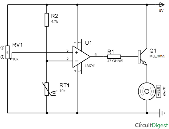
Here is a circuit that may work for you. I have a 10k thermistor and a MJE3055. I could try it on a breadboard if you like; converting it to 12v.
-

Circuit to increase CEMF spikes
Hamza Yapici replied to Kerrowman's topic in Electronic Projects Design/Ideas
I am not well in English but I recommend you use the snubber circuit. A high-watt resistor, a high-voltage capacitor, and a fast diode must be included. -
Hi guys) I am studying the topic of software and its testing. What can you tell me about errors and bugs? Who can I consult on this topic?
-
I want to build an electronic circuit to convert an NTC 10 kiloohm (B=3950) signal into an output voltage that can supply 2-3 amps. The output voltage should correspond to the measured temperature (4V at 25°C to 12V at 50°C), i.e. have a range of 4V to 12V DC. Is this typically done with a buck/boost converter and a coil and capacitor? Or is there a ready-made chip that I can use to achieve a maximum output voltage of 12V DC? The power supply comes from a PC power supply (12V DC). The purpose of the circuit is to control the speed of one or more DC fans using a changing operating voltage at the fan, without using PWM. To linearize the NTC and process the voltage, I was thinking of using a TLV9002 from TI. Can anyone help me with the rest of the circuit? No programming, no software, no Arduino, no PLSOC, just more or less classical built up with only a few compenents. Is that possible?
-
 Tajwar Kumar changed their profile photo
 -
 SHREYA AGRAWAL changed their profile photo
 -
 That is a linear supply, but what I posted here is switching and very small, you can embed it in whatever enclosure and control the voltage using the potentiometer
 -
With an electronic parts circuit you want a 100-watt supply with volts varying from 1 to 220 volts
-
 Good day! Thank you for the information.
 -
well..actually..i was told that it is a richtek R7731A. i was directed to these sites.... http://www.smdmark.com/en-US/search/code?id=dp%3D and https://www.s-manuals.com/smd From their datasheet the marking is really idp=W where W is a date code. chopper r7731a_richtek.pdf
-
I think you are right. Because I never came across such a strange marking on ICs before.
-
 Thanks for sharing the design and the video. I came across this design and found it good too: https://www.pcbway.com/project/shareproject/power_supply_0_30V_2mA_3A_version2_28ca8ff0.html But your power supply has a bigger voltage and current rating I can see.
 -
 If you get a "for parts or not working" power supply from certain reputable manufacturers you should be able to fix it. Make sure you can find the service manual and check it that the device does not have proprietary parts. Certain power supplies are so common repair parts are also common. I found a triple Sorensen XT power supply that already was 2/3 working units so I just fixed the part that wasnt and now I have a really solid triple supply. Apart from a hum (a physical hum, the DC output is incredibly quiet, as quiet as a battery) its perfect. But it weighs maybe 30 or 40 lbs. Its a real boat anchor. If it was bought 100% working it would have cost me at least $250 even used and >35 yrs old.
 -
 I didn’t find the library on GitHub, but thanks for the answer, now it’s clear which library is needed for such a project. I'm sorry, I did not notice that the topic is old ... I was just looking for data.
 -
Thank you!!! I was looking for this.
-
 PhoenixX1 reacted to a post in a topic:
Help needed
PhoenixX1 reacted to a post in a topic:
Help needed
-
A DC-to-DC converter is one of the most commonly used circuits in electronics, especially in power supply applications. There are three major types of DC-to-DC converters (non-isolated): Buck, Boost, and Buck-Boost. Sometimes a buck converter is also called a step-down converter and a boost converter is also called a step-up converter. In this article/video, I introduce an adjustable 5A DC-to-DC converter circuit that uses an advanced chip, made by Texas Instruments, which is TPS5450. It’s a high-frequency and efficient buck converter chip that provides tight voltage regulation. I have followed several PCB design rules to ensure low noise, low EMI, and high stability of the output voltage. To design the schematic and PCB, I used Altium Designer 23 and shared the project with my friends using Altium-365. The fast component search engine (Octopart) allowed me to quickly consider components’ information and also generate the BOM. To get high-quality fabricated boards, I sent the Gerber files to PCBWay and tested the circuit for output stability and noise, using a DC load, a multimeter, and an oscilloscope. Soon later, I will also perform the step-response test and demonstrate the results. Specifications Input Voltage: 5.5V to 36V Output Voltage: 1.22Vmin to 31Vmax (variable) Output Current (continuous): 5A Output Current (peak, short time): 6A Maximum Output Drop: 22mV (5A load) Output Noise: 14mVp-p (no load), 50mVp-p (5A load), 20MHz-BW References Full Article, Downloading PCB, Direct Order: https://www.pcbway.com/project/shareproject/5A_35V_Adjustable_Switching_Power_Supply_760ba488.html [1]: TPS5450: https://octopart.com/tps5450ddar-texas+instruments-7105511?r=sp [2]: SS56: https://octopart.com/ss56bf-hf-comchip-107339894?r=sp [3]: 3590-S2: https://octopart.com/3590s-2-502l-bourns-112621?r=sp
-

4CH LONGRANGE INFRARED REMOTE CONTROL
MrRich replied to Rathaur Rakesh's topic in Electronic Projects Design/Ideas
Where can I find the recommendations for a universal remote control? My Website: https://elpasoconcrete.weebly.com/ -
 How much is it?
 -
 Jonty Weyer changed their profile photo
 -
 Sindhu K reddy changed their profile photo
 -
 my website changed their profile photo
 -
 casinositezonecom changed their profile photo
 -
Harry, my friend... YOU... ARE... MY... HERO. That is exactly what I was looking for. I need to practice this stuff so I can do that on my own. It seems so simple when I see your rendering, but I was stumped on it. Thank you.


